On-site calibration method and equipment of marine fiber bragg grating strain sensor

A strain sensor, fiber grating technology, applied in the direction of optical devices, instruments, measuring devices, etc., can solve the problems of difficult to reach the test angle, can not achieve on-site calibration, affect the calibration results, etc., to achieve convenient calibration methods and improve calibration The effect of high accuracy and calibration accuracy

Inactive Publication Date: 2021-01-22
QUZHOU UNIV
View PDF7 Cites 6 Cited by
  • Summary
  • Abstract
  • Description
  • Claims
  • Application Information

AI Technical Summary

Problems solved by technology

[0005] The optical fiber of the fiber Bragg grating sensor is the detection of the optical fiber. It is a dielectric waveguide working in the light wave band, and the strain will directly affect the wavelength drift. Therefore, in the research and development of the ship monitoring and evaluation system, the calibration of the fiber Bragg grating strain sensor The direction is of great research significance; the traditional fiber grating sensor is usually calibrated by using a laser scanning lens and an excitation device for analog detection. This method often requires the use of large calibration equipment, resulting in the inability to achieve on-site calibration purpose, and the laser scanning lens is usually manually adjusted, it is difficult to achieve some small angle adjustments, which makes it difficult to achieve an accurate test angle; affects the calibration results

Method used


Image

  • On-site calibration method and equipment of marine fiber bragg grating strain sensor
  • On-site calibration method and equipment of marine fiber bragg grating strain sensor
  • On-site calibration method and equipment of marine fiber bragg grating strain sensor

Examples


Embodiment 1

[0049] The technical solution of the present invention is achieved in this way: a kind of on-site calibration method of marine fiber grating strain sensor is characterized in that: comprises the following steps:

[0050] S1 to establish a database: prepare the host computer, establish a database on the host computer, and set up electrical communication between the simulated board to be tested and the database;

[0051] S2 Installing the simulated board to be tested: bonding the simulated board to be tested with the optical fiber strain sensor installed on the ship to form equivalent strain;

[0052] S3 install the FBG demodulation instrument: connect the FBG strain sensor to the optical fiber joint of the FBG demodulation instrument through the transmission cable, and connect the FBG adjustment instrument to the upper electromechanical device through wires;

[0053] S4 determines the standard strain value: the strain value of the standard fiber grating sensor is measured in th...

Embodiment 2

[0063] A method for on-site calibration of a marine fiber grating strain sensor, characterized in that: comprising the steps of:

[0064] S1 to establish a database: prepare the host computer, establish a database on the host computer, and set up electrical communication between the simulated board to be tested and the database;

[0065] S2 Installing the simulated board to be tested: bonding the simulated board to be tested with the optical fiber strain sensor installed on the ship to form equivalent strain;

[0066] S3 install the FBG demodulation instrument: connect the FBG strain sensor to the optical fiber joint of the FBG demodulation instrument through the transmission cable, and connect the FBG adjustment instrument to the upper electromechanical device through wires;

[0067] S4 determines the standard strain value: the strain value of the standard fiber grating sensor is measured in the simulation test of the plate to be tested, and is recorded as Z1;

[0068] S5 st...

Embodiment 3

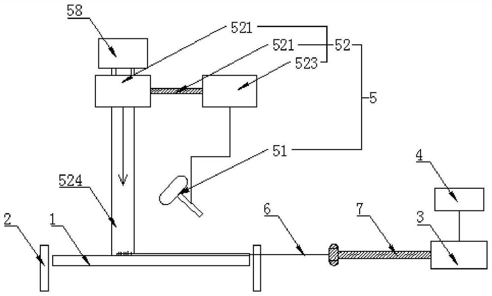
[0077] In addition, if Figure 1-2 As shown, the present invention also discloses a calibration device for a marine fiber grating strain sensor. In a specific embodiment of the present invention, it includes a simulated plate to be measured 1, a boundary support member 2, a fiber grating demodulation instrument 3, a host computer 4 and Simulated vibration analysis device 5.

[0078] Wherein, the laser lens is the PSV-400scanning head of Polytec Company; the laser scanner vibration test and analysis system is the OFV-5000vibrometer controller of Polytec Company; the model of the fiber grating solution instrument panel is SM130;

[0079] The simulated test board 1 is a rectangular flat plate of technical materials, which is installed on the boundary support member through connectors, and the optical fiber grating strain sensor to be detected is installed on the central position of the simulated test board 1 through glue, and is parallel to the simulated test board. The surface ...


PUM


Abstract

The invention relates to an on-site calibration method of a marine fiber bragg grating strain sensor. The method comprises the following steps of establishing a data preparing an upper computer,establishing the database on the upper computer, and setting electric communication between a simulated to-be-tested board and the database; mounting the simulated to-be-tested board: performing surface bonding on the simulated to-be-tested board and the fiber bragg grating strain sensor to form an equivalent strain; installing a fiber bragg grating demodulation instrument: connecting the fiber bragg grating strain sensor with the fiber bragg grating demodulation instrument; installing a simulated vibration analysis device; carrying out simulation analysis: obtaining the strain of the fiber bragg grating strain sensor for simulating the natural frequency vibration state of the to-be-tested board, determining the strain as calibration source data Z1, and storing the calibration source dataZ1 in a database; starting a fiber bragg grating demodulation instrument program to obtain actual strain data Z2 of the fiber bragg grating strain sensor; and carrying out comparison and calibration:displaying the data obtained in the steps S5 and S6 on a display screen of the upper computer, and performing comparison and calibration. The method is good in calibration effect and high in calibration precision.

Description

technical field [0001] The invention relates to the technical field of ship detection, in particular to an on-site calibration method and equipment for a ship-used optical fiber grating strain sensor. Background technique [0002] With the development of world trade and economy, the international shipping industry plays a vital role. The development of global economic integration is inseparable from the support of the shipping industry, and it also promotes the vigorous development of the shipping industry. Ships are an important means of transportation in the shipping industry, and their safety performance is also the focus of attention. The strength of the hull structure is one of the important factors that determine the safety performance of the ship. Classification societies have formulated relevant specifications and standards in the process of ship design and construction, and put forward relevant requirements and plans for the construction process and ship maintenance...

Claims


Application Information

Patent Timeline
Patent Type & Authority Applications(China)
IPC IPC(8): G01B11/16
CPCG01B11/16G01B21/042
Inventor 江舒李涛孟栋成胡伊吉海
Owner QUZHOU UNIV
Why Eureka
Try Eureka