Method, device and equipment for determining line transferable power supply rate and storage medium
A method of determining and transferring power supply technology, which is applied in the direction of instruments, data processing applications, office automation, etc., can solve problems such as heavy workload, difficulty in ensuring accuracy, and low efficiency in determining power supply capacity, so as to avoid errors, save manpower and Time, the effect of improving determination efficiency and calculation accuracy
- Summary
- Abstract
- Description
- Claims
- Application Information
AI Technical Summary
Problems solved by technology
Method used
Image
Examples
Embodiment 1
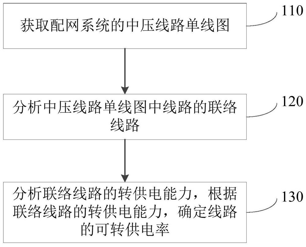
[0023] figure 1 It is a schematic flowchart of a method for determining the transferable power supply rate of a line provided by Embodiment 1 of the present invention. This embodiment is applicable to the calculation of the transferable power supply rate of a line. The method can be determined by the device for determining the transferable power supply rate of a line implement. Such as figure 1 As shown, the method specifically includes the following steps:
[0024] Step 110, acquiring a single-line diagram of a medium-voltage line of the distribution network system.
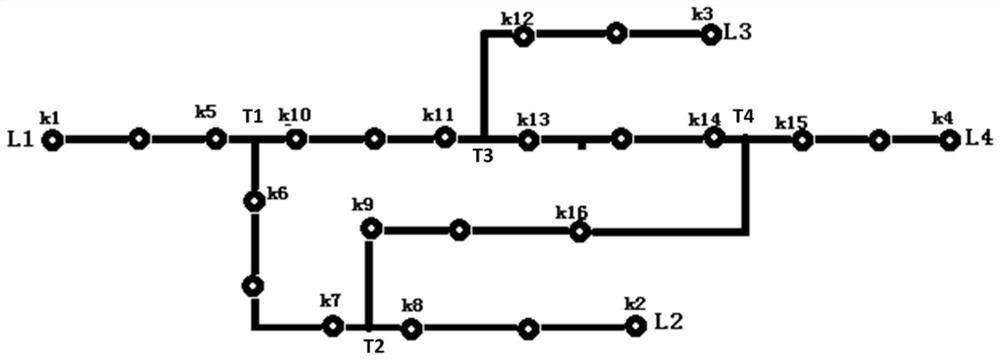
[0025] Wherein, the distribution network system may be a GIS (Geographic Information System, geographic information system) system, and the medium-voltage line single-line diagram may be used to represent the wiring situation of the power supply line in the power system. After the user issues an analysis command for transferring power supply capacity, the server automatically obtains the single-line diagram o...
Embodiment 2
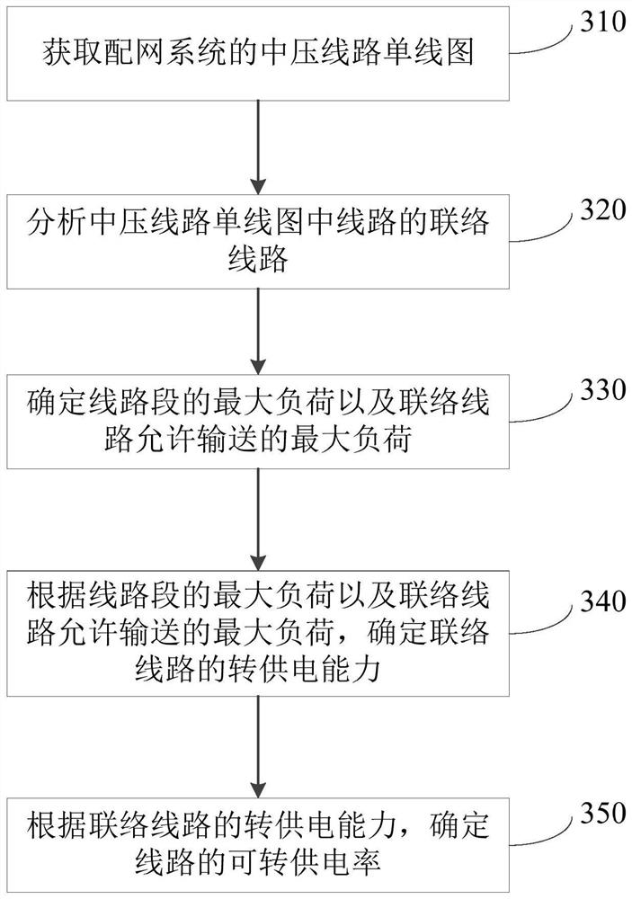
[0045] image 3 It is a schematic flowchart of a method for determining the transferable power supply rate of a line provided in Embodiment 2 of the present invention. This embodiment is further optimized on the basis of the above-mentioned embodiment. This method can be determined by a method for determining the transferable power supply rate of a line device to execute. Such as image 3 As shown, the method specifically includes the following steps:
[0046] Step 310, obtaining a single-line diagram of a medium-voltage line of the distribution network system.
[0047] Step 320 , analyzing the connecting lines of the lines in the single line diagram of the medium voltage line.
[0048] Step 330, determine the maximum load of the line segment and the maximum load allowed to be transported by the connection line.
[0049] Step 340: Determine the transfer power supply capacity of the tie line according to the maximum load of the line segment and the maximum load allowed to b...
Embodiment 3
[0115] Figure 4 It is a structural block diagram of a device for determining a switchable power supply rate of a line provided by an embodiment of the present invention, which can execute the method for determining a switchable power supply rate of a line provided in any embodiment of the present invention, and has corresponding functional modules and beneficial Effect. Such as Figure 4 As shown, the device specifically includes:
[0116] A line diagram acquisition module 401, configured to acquire a single-line diagram of a medium-voltage line of the distribution network system;
[0117] Tie line analysis module 402, configured to analyze the tie line in the single line diagram of the medium voltage line;
[0118] The transfer power supply rate determination module 403 is used to analyze the transfer power supply capacity of the connecting line, and determine the transferable power supply rate of the line according to the transfer power supply capacity of the tie line. ...
PUM
 Abstract
Description
Claims
Application Information
 - R&D
- Intellectual Property
- Life Sciences
- Materials
- Tech Scout
- Unparalleled Data Quality
- Higher Quality Content
- 60% Fewer Hallucinations
Browse by: Latest US Patents, China's latest patents, Technical Efficacy Thesaurus, Application Domain, Technology Topic, Popular Technical Reports.
© 2025 PatSnap. All rights reserved.Legal|Privacy policy|Modern Slavery Act Transparency Statement|Sitemap|About US| Contact US: help@patsnap.com


