Distribution box with wire passing hole

A technology of distribution box and wire hole, which is applied in the field of distribution box with wire hole, which can solve the problems of internal wire body influence, wire body looseness, and inability to guarantee safety, so as to ensure quality and stability Effect

Pending Publication Date: 2021-01-22
孝感航跃电气科技有限公司
View PDF0 Cites 2 Cited by
  • Summary
  • Abstract
  • Description
  • Claims
  • Application Information

AI Technical Summary

Problems solved by technology

[0002] The distribution box is a large number of parameters in the data. It generally constitutes a low-voltage distribution box. The distribution box can be connected or disconnected by manual or automatic switch during normal operation. The distribution box has the advantages of small size, easy installation, special technical performance, fixed position, unique configuration function, not limited by the site, common application, stable and reliable operation , high space utilization, less land occupation and environmental protection effect. During installation, it is necessary to penetrate the wire body from the wire hole into the inside of the distribution box for installation. The wire hole of the general distribution box is aligned with the wire body. The surface will cause wear and tear, and its safety cannot be guaranteed. If the wire hole is too large, birds will build nests, which will affect the connection of the internal wire body. When the door is closed, the power distribution box will vibrate and the connected wire The body is loose, so we need to design a distribution box with wire holes to solve these problems

Method used


Image

  • Distribution box with wire passing hole
  • Distribution box with wire passing hole
  • Distribution box with wire passing hole

Examples


Embodiment Construction

[0022] The following will clearly and completely describe the technical solutions in the embodiments of the present invention with reference to the accompanying drawings in the embodiments of the present invention. Obviously, the described embodiments are only some, not all, embodiments of the present invention. Based on the embodiments of the present invention, all other embodiments obtained by persons of ordinary skill in the art without making creative efforts belong to the protection scope of the present invention.

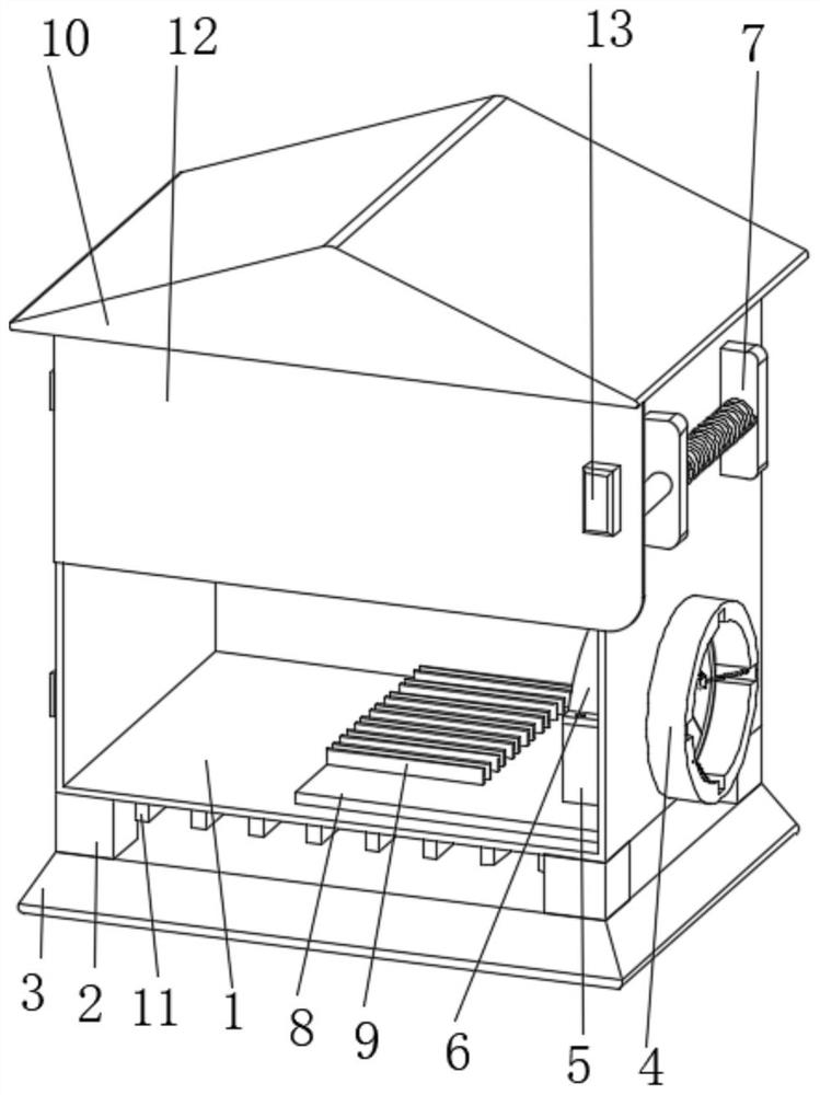
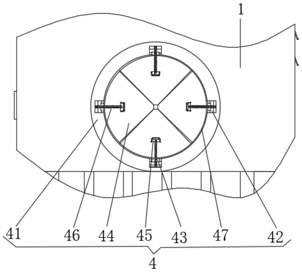
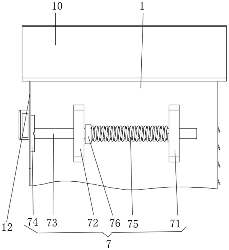
[0023] see Figure 1-4 , the present invention provides a technical solution: a distribution box with wire holes, including a box body 1, a stable structure 4 and a buffer structure 7;

[0024] Box 1: The lower surface is provided with evenly distributed support legs 2, the lower surface of the support legs 2 is fixedly connected with the upper surface of the base 3, the inner bottom of the box 1 is provided with a horizontal plate 8 on the right side of the m...


PUM


Abstract

The invention discloses a distribution box with a wire passing hole. The distribution box comprises a box body, a stabilizing structure and a buffer structure; uniformly distributed supporting legs are arranged on the lower surface of the box body, the lower surfaces of the supporting legs are fixedly connected with the upper surface of the base, a transverse plate is arranged on the right side ofthe middle of the inner bottom surface of the box body, uniformly distributed branching grooves are formed in the left side of the upper surface of the transverse plate, and the upper surface of thebox body is fixedly connected with the lower surface of a ceiling; the front side surface of the box body is hinged with a distribution box door through hinges, the left side of the front side surfaceof the distribution box door is provided with a box door handle, the right upper side of the front side surface of the distribution box door is provided with a box door lock. According to the distribution box with the wire passing hole, the quality of the surface of a wire body is guaranteed, high efficiency and stability are achieved, the wire body is sorted and arranged in order, loosening of the wire body connected in the box body due to large closing force is prevented, efficient buffering is achieved, the safety problem caused by rainwater entering is prevented, and effective heat dissipation is conducted on the temperature in the box body.

Description

technical field [0001] The invention relates to the technical field of distribution boxes, in particular to a distribution box with wire passing holes. Background technique [0002] The distribution box is a large number of parameters in the data. It generally constitutes a low-voltage distribution box. The distribution box can be connected or disconnected by manual or automatic switch during normal operation. The distribution box has the advantages of small size, easy installation, special technical performance, fixed position, unique configuration function, not limited by the site, common application, stable and reliable operation , high space utilization, less land occupation and environmental protection effect. During installation, it is necessary to penetrate the wire body from the wire hole into the inside of the distribution box for installation. The wire hole of the general distribution box is aligned with the wire body. The surface will cause wear and tear, and its...

Claims


Application Information

Patent Timeline
IPC IPC(8): H02B1/20H02B1/54H02B1/56H02B1/28H02B1/46H02B1/48H02B1/50H02G3/22H02G3/04
CPCH02B1/20H02B1/28H02B1/46H02B1/48H02B1/50H02B1/54H02B1/565H02G3/045H02G3/22
Inventor 孙美腾申丽丽孙凡凡孙志雄
Owner 孝感航跃电气科技有限公司
Why Eureka
Try Eureka