Automatic welding device for end flange of pipefitting

A technology of automatic welding and automatic welding, applied in auxiliary devices, welding equipment, auxiliary welding equipment, etc., can solve the problems of reducing welding efficiency, consuming manpower, and reducing welding quality.

Pending Publication Date: 2021-01-26
东营胜滋自动化科技有限责任公司
View PDF5 Cites 10 Cited by
  • Summary
  • Abstract
  • Description
  • Claims
  • Application Information

AI Technical Summary

Problems solved by technology

[0002] The flange connection at the end of the pipe fittings has the characteristics of easy disassembly, which is suitable for the connection of multiple disassembly connections. In the manufacturing plant, the pipe fittings and flanges are mostly welded. Due to the lack of special welding machines, the pipe fittings are generally placed on the ground. Align and press the pipe fittings and flanges with manual clamps on the upper or supporting platform. When the pipe

Method used


Image

  • Automatic welding device for end flange of pipefitting
  • Automatic welding device for end flange of pipefitting
  • Automatic welding device for end flange of pipefitting

Examples


Embodiment Construction

[0039] The following will clearly and completely describe the technical solutions in the embodiments of the present invention with reference to the accompanying drawings in the embodiments of the present invention. Obviously, the described embodiments are only some, not all, embodiments of the present invention. The following description of at least one exemplary embodiment is merely illustrative in nature and in no way taken as limiting the invention, its application or uses. Based on the embodiments of the present invention, all other embodiments obtained by persons of ordinary skill in the art without creative efforts fall within the protection scope of the present invention.

[0040] The relative arrangements of components and steps, numerical expressions and numerical values ​​set forth in these embodiments do not limit the scope of the present invention unless specifically stated otherwise. At the same time, it should be understood that, for the convenience of descriptio...


PUM


Abstract

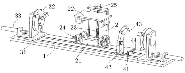
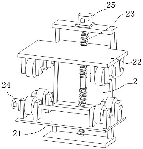
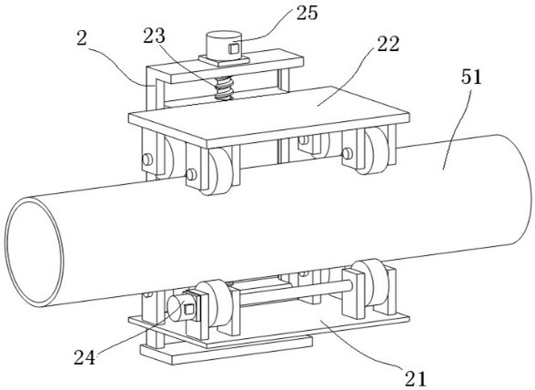
The invention relates to the technical field of welding automation and provides an automatic welding device for an end flange of a pipefitting. The device comprises a pipefitting rotating unit, a flange supporting unit and a welding gun operating unit. The pipefitting rotating unit is arranged in the middle of a base for clamping and rotatably driving the pipefitting to be welded, and a rack is provided with a centering and clamping driving mechanism for driving a lower roller set and an upper roller set to move synchronously and reversely; the flange supporting unit is arranged at a longitudinal outer end of the base for clamping the flange to be welded and comprises a movable seat and a chuck, and the base is provided with a linear power part for driving the movable seat to move longitudinally; and the welding gun operating unit is arranged on the outer side of the base for moving the automatic welding gun. The automatic welding device for the end flange of the pipefitting can realize clamping, abutting and automatic welding operations of the pipefittings with different lengths and outer diameters to flanges, so that the device is easy to operate, high in degree of automation andsuitable for being applied to operational occasions of welding the pipefittings to the flanges.

Description

technical field [0001] The invention relates to the technical field of welding automation, in particular to an automatic welding equipment for welding the circular welds between pipe fitting ends and flanges. Background technique [0002] The flange connection at the end of the pipe fittings has the characteristics of easy disassembly, which is suitable for the connection of multiple disassembly connections. In the manufacturing plant, the pipe fittings and flanges are mostly welded. Due to the lack of special welding machines, the pipe fittings are generally placed on the ground. Align and press the pipe fittings and flanges with manual clamps on the upper or supporting platform. When the pipe fittings and flanges are in a static state, the welding worker holds an automatic welding torch to fix the pipe fittings and flanges by spot welding, and then assembles and disassembles the fixtures. The hand-held automatic welding torch is used to complete the welding of the circular...

Claims


Application Information

Patent Timeline
IPC IPC(8): B23K37/02B23K37/053B23K37/00B23K101/06
CPCB23K37/0211B23K37/0252B23K37/0536B23K37/0538B23K37/00B23K2101/06
Inventor 不公告发明人
Owner 东营胜滋自动化科技有限责任公司
Why Eureka
Try Eureka