
Plate drilling workbench with fool-proof design and drilling method thereof

A drilling method and a workbench technology, applied in the direction of manufacturing tools, fixed drilling machines, wood processing appliances, etc., can solve the problems of unfriendliness for beginners, time-consuming, prolonging processing time, etc., to reduce adverse effects and reduce manufacturing costs , Easy to clean effect

Active Publication Date: 2022-02-11
ZHONGSHAN XIWEI KITCHEN EQUIP MFG
View PDF10 Cites 0 Cited by
  • Summary
  • Abstract
  • Description
  • Claims
  • Application Information

AI Technical Summary

Problems solved by technology

Punch and drill this type of stepped hole (such as Figure 4 The process shown) is cumbersome and tests the skills of the operator. It is necessary to repeatedly adjust the position of the drill bit, and it is difficult to control the length and depth of the drill hole, which is not friendly to novices. In actual processing, a large number of repeated punching and drilling of the same standard It takes a lot of time to repeatedly adjust the position of the engraving machine drill bit and repeatedly measure the moving distance, thereby prolonging the processing time and reducing the processing efficiency.

Method used


Image

  • Plate drilling workbench with fool-proof design and drilling method thereof
  • Plate drilling workbench with fool-proof design and drilling method thereof
  • Plate drilling workbench with fool-proof design and drilling method thereof

Examples


Embodiment Construction

[0035] In order to make the objects, technical solutions and advantages of the present invention, the present invention will be described in detail below with reference to the accompanying drawings and examples. It is to be understood that the specific embodiments described herein are intended to explain the present invention and is not intended to limit the invention.

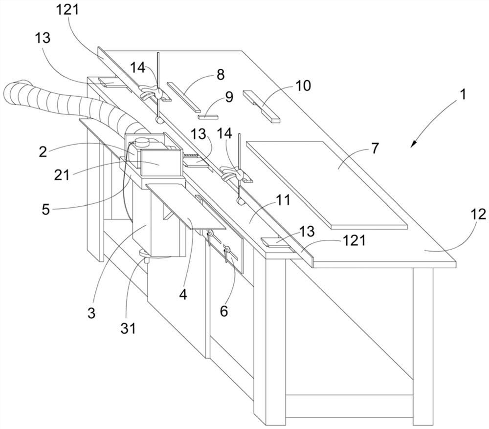
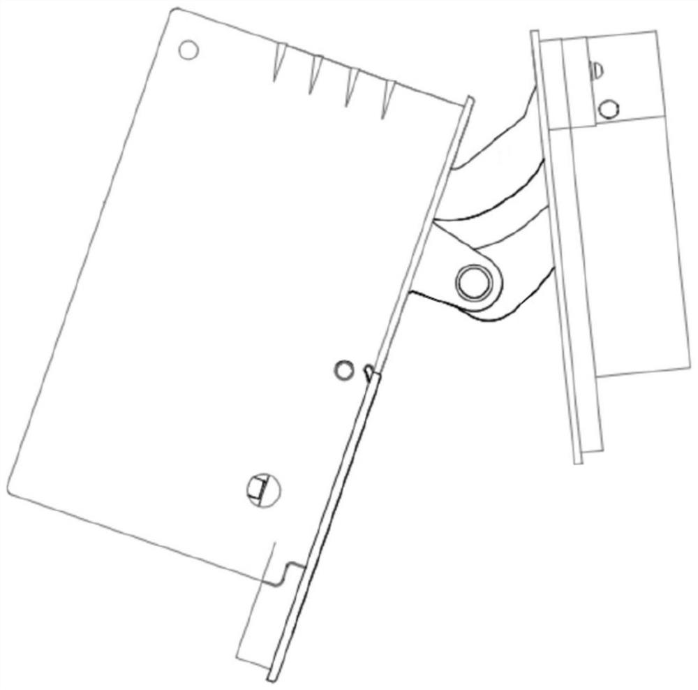
[0036] like figure 1 As shown, the preferred embodiment of the present invention has a plate drilling workbench with a stretch design, and its stiff design is mainly for repeated drilling. image 3 The hinge hole adapted to the heaven and earth hinge, the desired drilling type is a step 71, such as Figure 4 The step hole 71 has a deep hole 711 and a shallow groove 712, the length of the deep hole 711 is L1, the depth is D1; ​​the length of the shallow groove 712 is L2, the depth is D2; the deep hole 711 and the shallow groove 712 are between The length difference is a, the depth difference is b, that is, A = L2-L1,...


PUM


Abstract

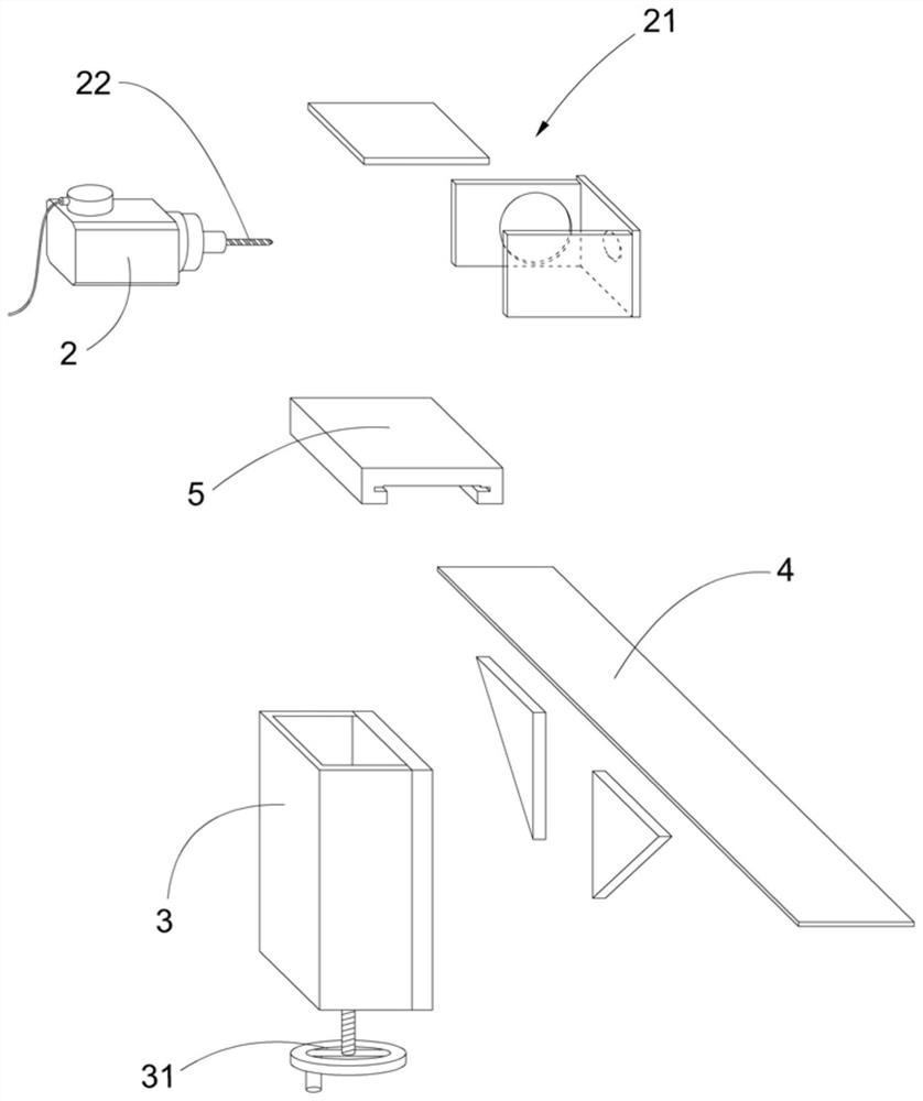
The invention provides a plate drilling workbench with a fool-proof design, including a workbench and an engraving machine, a screw box is fixed on the front side of the workbench, a screw is installed vertically in the screw box, and the top of the screw is connected to a horizontally installed lifting plate. The screw drives the lifting plate to move up and down. The lifting plate is covered with a side slider that can slide relative to its extension direction. The side slider is equipped with an engraving machine. The two ends of the front side of the workbench are respectively equipped with side movement limit plates. Two sideslip holes are set on the side movement limiting plate, and a tightening handle is installed on the front side of the workbench to pass through the side sliding holes. Sliding in the direction of hole extension, two side movement limit plates are provided with a resisting end near the end of the side slider, which is used to resist the movement of the side slider to limit the length of the drilled hole. The invention has a fool-proof design, which is faster and more convenient when repeatedly punching and drilling a single stepped hole, without repeated measurement to determine the distance, thereby improving the processing efficiency and reducing the error rate in actual production.

Description

Technical field [0001] The present invention relates to a furnished processing apparatus, and more particularly to a plate drilling apparatus. Background technique [0002] In the furniture industry, the production process of the door needs to be processed on the plate, including drilling on the side of the sheet to mount the hinge, a variety of hinges in the market, depending on the type of hinge, the hinge on the side of the corresponding floor material The type of hole is also different, the heave and earth hinge in the dark hinge (eg image 3 The hinge hole shown is a step hole, such as the patent disclosure, is disclosed, disclosed in CN 108049748A. Drilling this type of step hole (such as Figure 4 The process shown) is more cumbersome and tests the operator's skills. It needs to repeatedly debug the position of the drill bit, and the length and depth of the drilling are more difficult to control, and the novice is not friendly. In the actual processing, it will generally rep...

Claims


Application Information

Patent Timeline
Patent Type & Authority Patents(China)
IPC IPC(8): B27C3/02B27G3/00
CPCB27C3/02B27G3/00
Inventor 杨炼
Owner ZHONGSHAN XIWEI KITCHEN EQUIP MFG
Learn More