3D printing path generation method employing parallel modeling and slicing

A 3D printing and path generation technology, applied in the field of 3D printing, can solve the problems of low degree of automation, low efficiency, poor structural performance of printed products, etc., to achieve the effect of fast program, accurate data and saving running time

Active Publication Date: 2021-01-26
TONGJI UNIV
View PDF10 Cites 7 Cited by
  • Summary
  • Abstract
  • Description
  • Claims
  • Application Information

AI Technical Summary

Problems solved by technology

[0002] 3D printing technology is developing rapidly and has a wide range of application prospects. 3D printing is also called additive manufacturing. It is a "growth" method of building parts, so the process of "building a model" and the process of "generating a printing path" should be coordinated, that is, wherever the model is built, it will be printed there, but now Some 3D printing solutions are divided into two steps: modeling and slicing. The former uses CAD modeling software, while the latter uses independent slicing software. Only the final outline of the modeling is obtained, and its construction sequence and design intent cannot be understood, resulting in a single slicing algorithm and poor structural performance of the printed product. The sub-area and multi-directional construction technology based on multi-axis printers still uses independent modeling and slicing schemes. However, it relies on manually dividing the printing area and setting the construction direction, which partially solves the problem of support and interference, but the degree of automation is not high and the efficiency is low

Method used


Image

  • 3D printing path generation method employing parallel modeling and slicing
  • 3D printing path generation method employing parallel modeling and slicing
  • 3D printing path generation method employing parallel modeling and slicing

Examples


Embodiment

[0037] The present invention aims to develop a 3D printing path generation method that utilizes the sweeping modeling concept of variable cross-section to operate the modeling process and the printing path generation process in parallel, and realize surface slicing and multi-directional printing based on the multi-degree-of-freedom printing system. Taking the double-way elbow model as a demonstration case, the whole process of generating G code from the model is realized, and the operation results are simulated with CAM software, which proves the feasibility of the method.

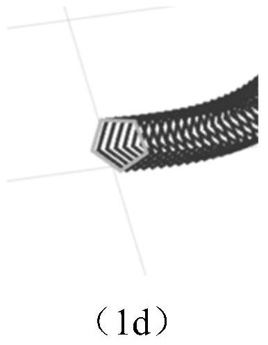
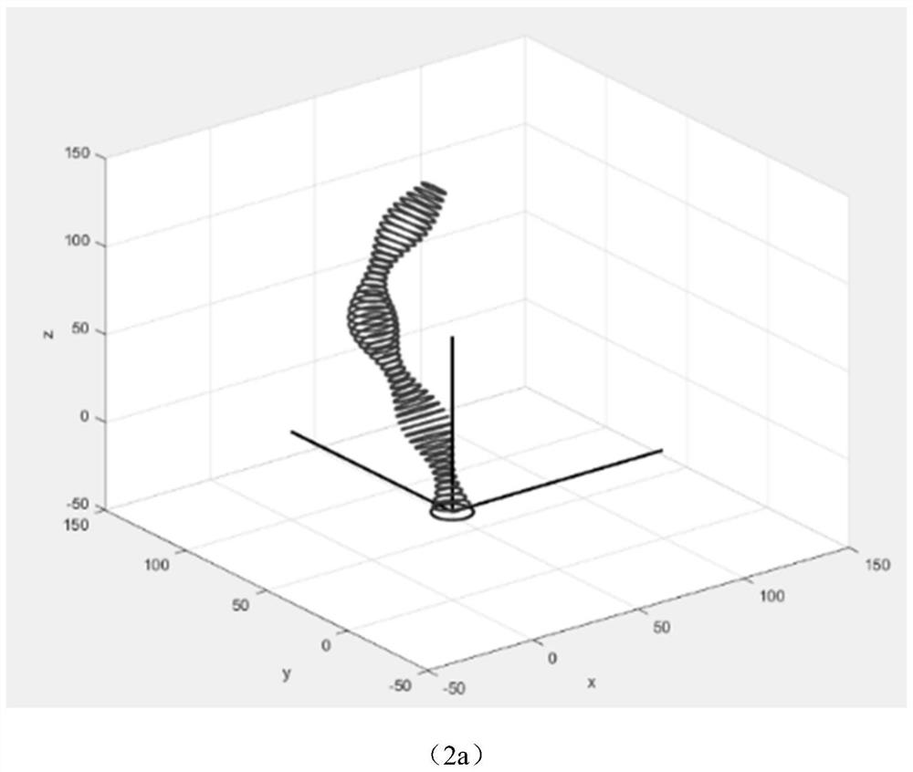
[0038] (1) Method flow, such as figure 1 and 4 as shown, figure 1 The curve in a is the sweeping path, the bottom circle is the initial layer section, and the top pentagon is the termination layer section. The printing path is calculated from the bottom circle until the top pentagon ends, and the variable section is achieved by interpolation. Transition effect, during the printing process, based on the d...


PUM


Abstract

The invention relates to a 3D printing path generation method employing parallel modeling and slicing. The method comprises the following steps of: 1) drawing a sweeping path; 2) carrying out discretization to form ordered path points and storing coordinates of various path points; 3) establishing a vector and representing the axis direction from a Pi section to a Pi+1 section through the vector vi; 4) constructing a Rodrigues rotation matrix R, and obtaining a rotation axis k and a rotation angle thetai of spatial rotation change of the Rodrigues rotation matrix R; 5) acquiring section contours of a starting layer and a stop layer; 6) solving point sets of the sections of intermediate layers; 7) repeating the calculation in the step 6), and sequentially solving the point sets of the sections of the intermediate layers; 8) carrying out translation and rotation transformation on the point sets of various layers according to a rotation formula to obtain a space coordinate set M of a final model; and 9) realizing 3D printing employing parallel modeling and slicing according to the corresponding transformation between double-cradle five-axis coordinates and a direct coordinate system.Compared with the prior art, the method has the advantages that slicing and modeling are carried out simultaneously, and the method is suitable for various models.

Description

technical field [0001] The invention relates to the technical field of 3D printing, in particular to a method for generating a 3D printing path in parallel with modeling and slicing. Background technique [0002] 3D printing technology is developing rapidly and has a wide range of application prospects. 3D printing is also called additive manufacturing. It is a "growth" method of building parts, so the process of "building a model" and the process of "generating a printing path" should be coordinated, that is, wherever the model is built, it will be printed there, but now Some 3D printing solutions are divided into two steps: modeling and slicing. The former uses CAD modeling software, while the latter uses independent slicing software. Only the final outline of the modeling is obtained, and its construction sequence and design intent cannot be understood, resulting in a single slicing algorithm and poor structural performance of the printed product. The sub-area and multi-...

Claims


Application Information

Patent Timeline
Patent Type & Authority Applications(China)
IPC IPC(8): B29C64/386B29C64/393B33Y50/00B33Y50/02G06T17/20
CPCB33Y50/00B33Y50/02B29C64/386B29C64/393G06T17/20G06T2200/04
Inventor 王玉王硕李帅帅张强于颖张晓阳
Owner TONGJI UNIV
Why Eureka
Try Eureka