Novel spinning type rocker arm ejection head clamping device

A clamping device, a new type of technology, applied in textiles and papermaking, continuous winding spinning machines, spinning machines, etc., can solve the problems of inconvenient weight operation, eccentric wear of the bobbin port, and poor yarn roll forming. , to achieve the effect of good concentricity, reduced vibration and noise of the machine, and easy operation.

Pending Publication Date: 2021-01-26
SUZHOU IMAGIN MACHINERY
View PDF0 Cites 1 Cited by
  • Summary
  • Abstract
  • Description
  • Claims
  • Application Information

AI Technical Summary

Problems solved by technology

[0007] The object of the present invention is to provide a novel spinning rocker arm clamping device to solve the problem that the rocker-arm type bobbin clamping structure proposed in the above-mentioned background technology is in the process of clamping, because its side angle is movable. The concentricity of the plugs at both ends will be poor after being clamped for a period of time, which will cause the bobbin to be clamped and deflected, resulting in partial wear of the bobbin end and poor yarn roll formation. It is very inconvenient to take the yarn. Due to the lack of a limit structure, the operator can only hold the support on one side of the rocker arm, and then take the yarn roll on the top of the other side. When the weight is too heavy, it will be very inconvenient to operate, and the labor burden is also relatively large.

Method used


Image

  • Novel spinning type rocker arm ejection head clamping device
  • Novel spinning type rocker arm ejection head clamping device
  • Novel spinning type rocker arm ejection head clamping device

Examples


Embodiment Construction

[0028] The following will clearly and completely describe the technical solutions in the embodiments of the present invention with reference to the accompanying drawings in the embodiments of the present invention. Obviously, the described embodiments are only some, not all, embodiments of the present invention. Based on the embodiments of the present invention, all other embodiments obtained by persons of ordinary skill in the art without making creative efforts belong to the protection scope of the present invention.

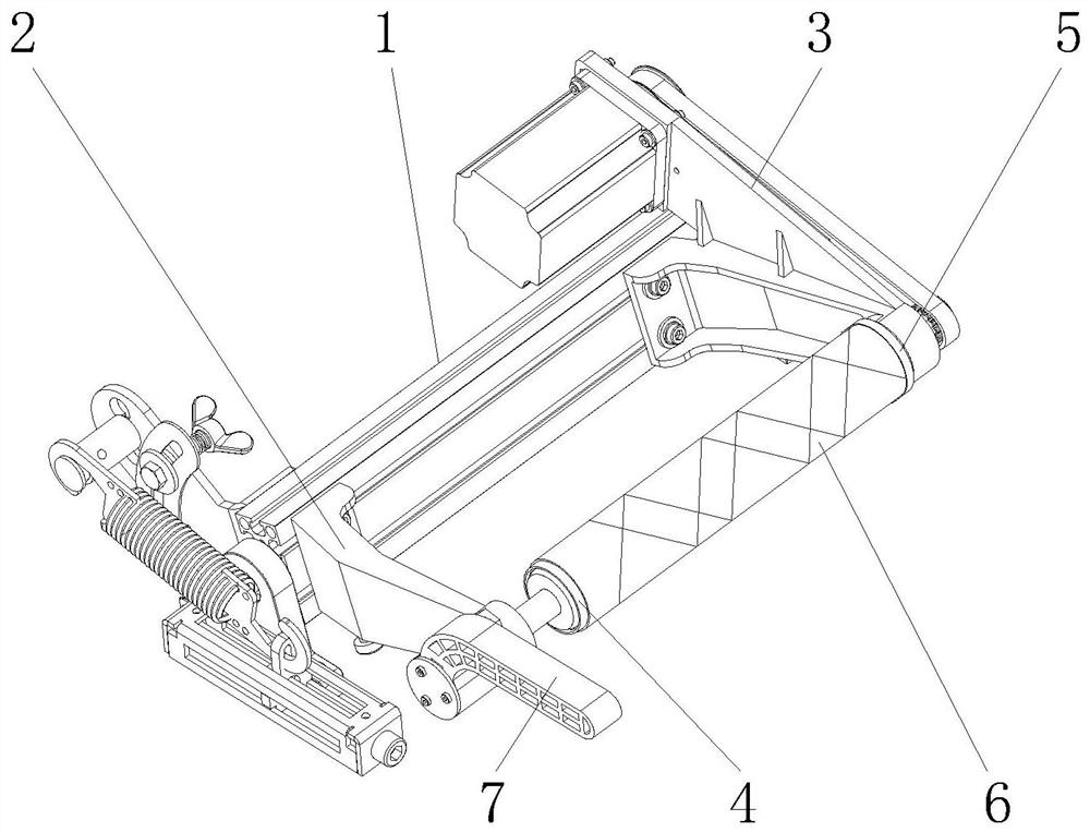
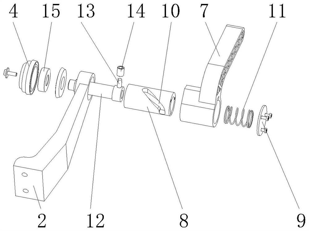
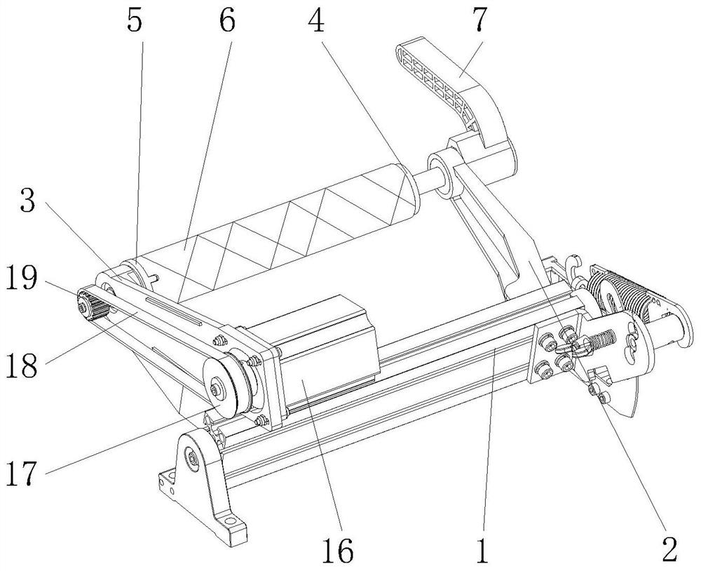
[0029] see Figure 1-10 , the present invention provides a technical solution: a novel spinning rocker head clamping device, including a mounting plate 1, a left bracket 2, a right bracket 3, a left head 4, a right head 5, a bobbin 6, a spinning Pressure handle 7, guide sleeve 8, end cap 9, side chute 10, limit spring 11, guide shaft 12, side slide bar 13, positioning bearing 14, internal bearing 15, motor 16, drive turntable 17, transmission belt 18. Transmi...


PUM


Abstract

The invention discloses a novel spinning type rocker arm ejection head clamping device. The device comprises a mounting plate, a spinning handle and a motor, wherein a left support and a right supportare mounted on the left side and the right side of the mounting plate respectively; the spinning handle is rotationally mounted on the side face of the left support; a guide sleeve is mounted on theinner side of the spinning handle; an end cover is connected with a guide shaft through a limiting spring; the side face of the guide shaft is connected with a left ejection head through an internal bearing; the motor is fixedly mounted on the side face of the right support; a driving rotary disc is rotationally mounted on the outer side face of the right support; a positioning plate is fixedly mounted on the outer side face of the mounting plate; fixing frames are symmetrically arranged on the two sides of the exterior of the mounting plate; and sliding rails are welded to the outer side faces of the fixing frames. According to the novel spinning type rocker arm ejection head clamping device, novel structural design is adopted, so that a bobbin can be coaxially mounted in the device, andabrasion of the two ends of the bobbin in a machining process is reduced; and a spinning adjusting structure is convenient to operate, so that a worker can conveniently perform adjustment and control.

Description

technical field [0001] The invention relates to the technical field of rocker arm plugs of doubling machines, in particular to a novel spinning type rocker arm plug clamping device. Background technique [0002] At present, the general rocker-type head bobbin clamping technology principle adopted by doubling machines and winding machines on the market uses end rocker brackets to fix the bobbin ends, and fixes them through the positive pressure and friction force of the end taper head. Hold the bobbin so that the bobbin and the winding motor shaft maintain a consistent rotation, and the pressure rebound device keeps the rocker arm bracket and the end taper head reset in time to maintain the extrusion force on the bobbin. [0003] With the continuous installation and use of the plug clamping device, the following problems were found during use: [0004] 1. During the clamping process of the rocker-arm type bobbin clamping structure, because its side angle is movable, the conc...

Claims


Application Information

Patent Timeline
Patent Type & Authority Applications(China)
IPC IPC(8): D01H1/36
CPCD01H1/36
Inventor 王俭姚卫康
Owner SUZHOU IMAGIN MACHINERY
Why Eureka
Try Eureka