DMD-based spectral imaging target detection method and system

A target detection and spectral imaging technology, applied in the field of spectral imaging, can solve the problems of a single scanning area and a large amount of useless data, and achieve the effect of improving efficiency, reducing the amount of data for processing and analysis, and facilitating rapid collection.

Active Publication Date: 2021-01-26
宁波启朴芯微系统技术有限公司
View PDF15 Cites 2 Cited by
  • Summary
  • Abstract
  • Description
  • Claims
  • Application Information

AI Technical Summary

Problems solved by technology

[0006] The technical problem to be solved by the present invention is to provide a DMD-based spectral imaging target detection method, which obtains the low-resolution three-dimensional data cube and The high-resolution three-dimensional data cube of useful targets, this method is flexible and targeted, can remove redundant data volume, realize rapid positioning and accurate detection of useful targets in unknown scenes, and overcome the existing DMD-based scanning spectral imaging The method has defects such as detection blindness, large amount of useless data, and single scanning area, which is conducive to improving the efficiency of local target detection and recognition

Method used


Image

  • DMD-based spectral imaging target detection method and system
  • DMD-based spectral imaging target detection method and system
  • DMD-based spectral imaging target detection method and system

Examples


Embodiment 1

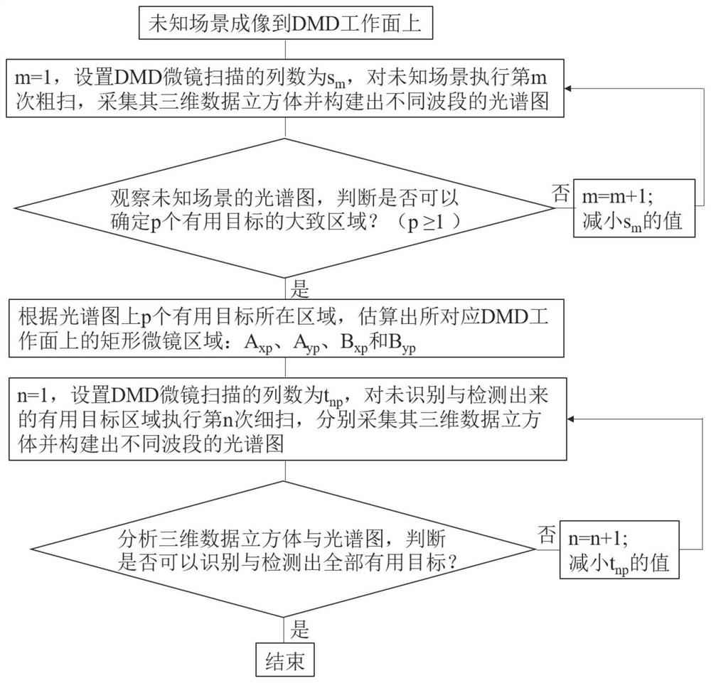
[0040] The present embodiment proposes a DMD-based spectral imaging target detection system and its implementation method. The micromirror array on the DMD working surface is 1024x768. At this time, A n =1024,B n =768. By controlling the DMD3 to conduct a low-resolution global rough scan on the image formed by the unknown scene 1, determine the approximate area of ​​the image of the three useful targets on the DMD working surface 4, reduce the bandwidth of the micromirror scan, and then use it Performing one high-resolution fine scan in the area can obtain enough useful information to realize the detection and identification of all useful targets. At this time, m=1, p=3, n=1. refer to image 3 Shown in the flowchart, the method specifically includes the following steps:

[0041] Step 1: The unknown scene 1 is imaged on the DMD working surface 4 through the imaging subsystem 2;

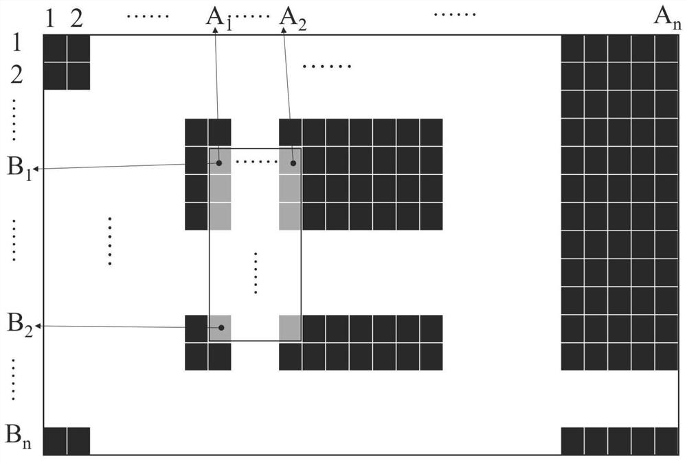
[0042] Step 2: See Figure 4 , set the number of columns scanned by the micromirror to 16, at ...

Embodiment 2

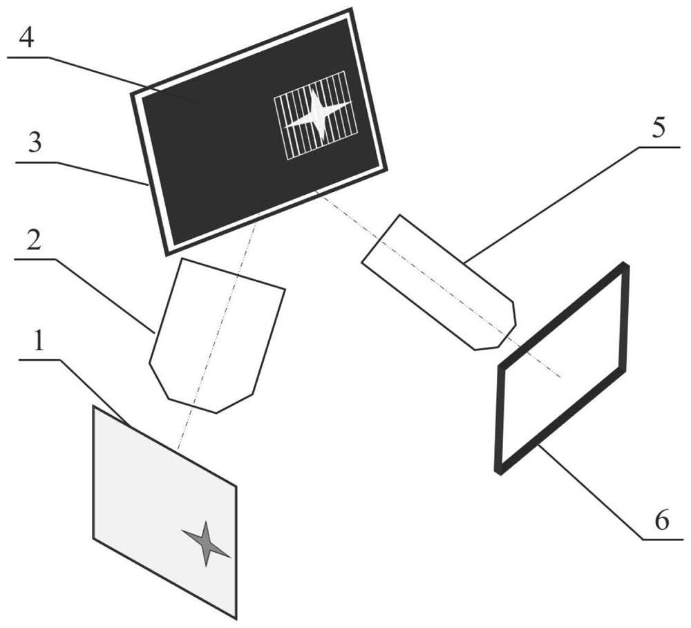
[0047] The composition of the DMD-based spectral imaging target detection system proposed in this embodiment is as follows: figure 1As shown, it mainly includes an unknown scene 1, an imaging subsystem 2, a DMD 3, a DMD working surface 4, a photo-splitting subsystem 5 and a detector 6. The unknown scene 1 and the DMD working surface 4 are respectively located at the object plane and the image plane of the imaging subsystem 2 , and the detector 6 is located at the image plane of the photo-splitting subsystem 5 . The imaging subsystem 2 converges the magnified image of the unknown scene 1 on the DMD working surface 4, and the working micromirror on the DMD working surface 4 reflects the image formed by the selected scene to the spectroscopic subsystem 5 for collimation and dispersion and focusing, the resulting dispersion spectrum is converged on the detector 6 and recorded, and the working state of the micromirror on the DMD working surface 4 is controlled by a computer.

[00...


PUM


Abstract

The invention relates to a DMD-based spectral imaging target detection method and system, and the method comprises the steps: controlling a DMD to carry out the m times of low-resolution global roughscanning (m is greater than or equal to 1) of an image formed by an unknown scene, determining an approximate region (p is greater than or equal to 1) of p useful target images on a DMD working surface, reducing the bandwidth of micro-mirror scanning, and performing high-resolution fine scanning (n is greater than or equal to 1) on the useful area for n times so as to acquire enough useful information, and detection and identification of all local useful targets in an unknown scene can be realized.

Description

technical field [0001] The invention belongs to the technical field of spectral imaging, and in particular relates to a DMD-based spectral imaging target detection method and system. Background technique [0002] Spectral imaging technology has the advantage of "map-spectrum integration", which can collect two-dimensional spatial information and one-dimensional spectral information of the target at the same time, so as to obtain a complete three-dimensional data cube. It has a wide range of applications in many fields. However, in many practical applications, the proportion of useful objects in the entire field of view is not large, and most of the areas are useless backgrounds, which causes the proportion of useless data in the entire 3D data cube to be too high. It is not conducive to the rapid compression, transmission, storage and processing of useful data, especially for hardware equipment and software algorithms such as data compression and transmission of remote sens...

Claims


Application Information

Patent Timeline
Patent Type & Authority Applications(China)
IPC IPC(8): G01B11/24
CPCG01B11/24
Inventor 虞益挺董雪仝赓
Owner 宁波启朴芯微系统技术有限公司
Why Eureka
Try Eureka