Bridge wind tunnel wind speed and vehicle force measurement test system and method

A force measurement test and wind tunnel technology, which can be used in vehicle testing, aerodynamic testing, and machine/structural component testing. , to reduce manual interference, improve efficiency and accuracy, and reduce the number of times

Pending Publication Date: 2021-01-26
XIAMEN UNIV OF TECH
View PDF0 Cites 0 Cited by
  • Summary
  • Abstract
  • Description
  • Claims
  • Application Information

AI Technical Summary

Problems solved by technology

However, manually moving the measuring equipment, on the one hand, cannot guarantee the accuracy of the moving position; on the other hand, in the process of moving the sensor, because of the need for personnel to enter and leave the laboratory, the fan and other equipment have to be temporarily stopped, which will make it difficult to guarantee the speed measurement. And the uniformity of the flow conditions of the force test, and consume a lot of time, in the current heavy scientific research tasks, this will occupy too much laboratory resources and increase the cost of the test

Method used


Image

  • Bridge wind tunnel wind speed and vehicle force measurement test system and method
  • Bridge wind tunnel wind speed and vehicle force measurement test system and method
  • Bridge wind tunnel wind speed and vehicle force measurement test system and method

Examples


Embodiment 1

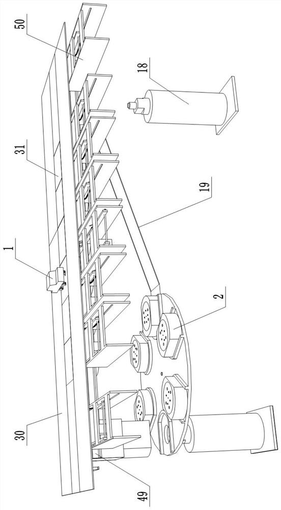
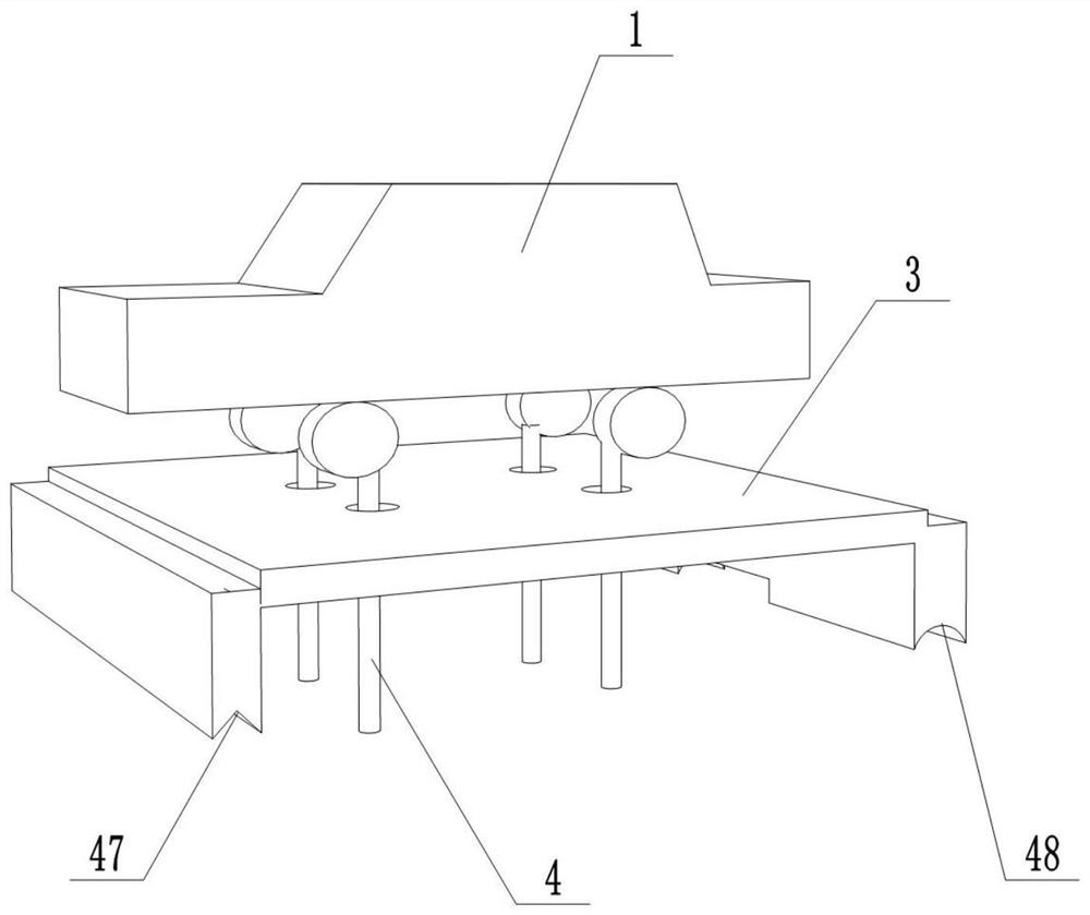
[0068] Such as Figure 1-Figure 5a , Figure 6-Figure 11a , Figure 12-Figure 14 Shown: This embodiment provides a kind of bridge wind tunnel wind speed and vehicle force measurement test system, comprises vehicle model 1, force balance 2, wind measurement platform and force measurement platform, and wind measurement platform comprises wind measurement crane, wind measurement The platform is set inside the wind tunnel and used to measure wind speed and wind direction at different positions. The force measuring platform is set inside the bridge model. The force measuring platform includes a mechanical servo system. The vehicle model 1 is locked on the force measuring balance 2, and the force measuring balance 2 is used for For measuring the six-component force of the vehicle model 1, a mechanical servo system is used to transport and move the force measuring balance 2. In this embodiment, through the cooperation of the wind measuring platform and the force measuring platform,...

Embodiment 2

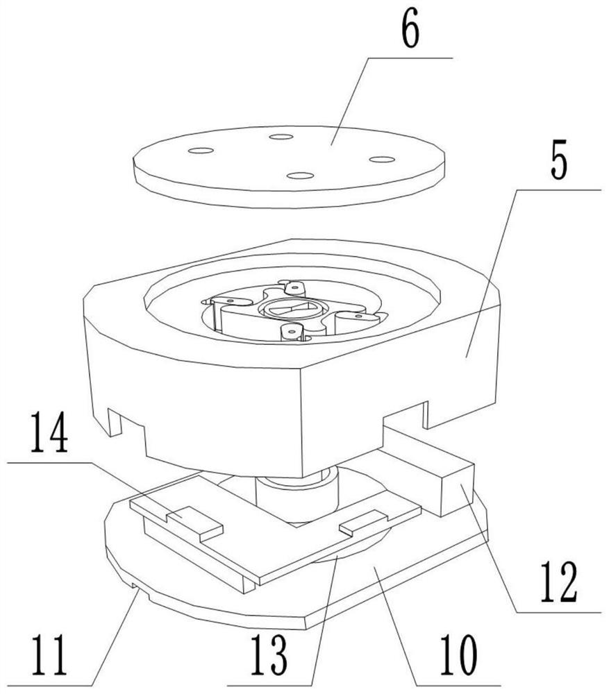
[0088] Such as Figure 5bAs shown, the difference between this embodiment and Embodiment 1 is that the clamping device also includes a locking pressure plate 15 and a pressure plate 52, the locking pressure plate 15 is arranged outside the locking groove 8, and the pressure plate 52 is arranged on the locking pressure plate 15 The outer side of the plate 52 is fixedly connected with the locking pressure plate 15, and the edge of the pressure plate 52 is provided with four protrusions, and each protrusion is in contact with a load cell 4. Inserting the locking groove 8 through the lifting rod key plate 9 drives the locking pressure plate 15 and the pressure plate 52 to rotate at a certain angle, and each protrusion presses the force measuring rod 4 into the draw-in groove of the force measuring inner ring 7 .

Embodiment 3

[0090] Such as Figure 11b As shown, the difference between this embodiment and Embodiment 1 or Embodiment 2 is that a sliding platform is provided on the force measuring platform, and the sliding platform includes fixed cover plates 30 on both sides of the force measuring platform and several sliding panels on the force measuring platform. Cover plate 31, each sliding cover plate 31 is all driven by a sliding mechanism 50; Each sliding mechanism all 50 comprises the second cover plate motor 53, lifting structure, push rod 54 and base 55, the slide rail seat of lifting structure and base 55 Sliding connection; the lifting structure includes two groups of symmetrically arranged connecting rod groups, each connecting rod group includes a first connecting rod 56, a second connecting rod 57, a third connecting rod 58 and a fourth connecting rod 59, and the first connecting rod 56 Set in parallel with the third connecting rod 58, the second connecting rod 57 and the fourth connecti...


PUM


Abstract

The invention discloses a bridge wind tunnel wind speed and vehicle force measurement test system and method, and relates to the technical field of bridge wind engineering. The system comprises a vehicle model, a wind measurement platform and a force measurement platform, wherein the wind measurement platform is arranged in the wind tunnel, comprises a wind measurement crown block and is used formeasuring wind speeds and wind directions at different positions; the force measurement platform is arranged in the bridge model and comprises a force measurement balance and a mechanical servo system, and the vehicle model is locked on the force measurement balance, so that the six-component force of the vehicle model can be conveniently collected in time in the test process; and the mechanical servo system is used for conveying and moving the force measurement balance. Through the cooperation of the wind measurement platform and the force measurement platform, the wind speed and direction ofeach lane and the corresponding vehicle model six-component force under each working condition can be continuously and synchronously acquired at any time, the frequency of adjusting the working condition and equipment by stopping a wind tunnel is reduced, the manual interference is reduced, and the test efficiency and precision are improved.

Description

technical field [0001] The invention relates to the technical field of bridge wind engineering, in particular to a bridge wind tunnel wind speed and vehicle force measurement test system and method. Background technique [0002] In bridge wind engineering research, in order to compare the advantages and disadvantages of different schemes, the same or several physical quantity measurement experiments of different model schemes are often carried out. In bridge speed test and vehicle dynamometer test, in order to measure the wind speed at points near the model and the six-component force of vehicles in different lanes under different model schemes, the wind speed at different positions and different lanes and vehicle forces are mainly measured by anemometers and force balances. Six-component force measurement for car model scheme. [0003] At present, the wind tunnel test mainly realizes the position movement of the wind speed measuring instrument and the force measuring balan...

Claims


Application Information

Patent Timeline
Patent Type & Authority Applications(China)
IPC IPC(8): G01M9/06G01M9/04G01M17/007
CPCG01M9/04G01M9/062G01M17/007
Inventor 林晓波林立袁志群吕恒庆胡磊胡海涛王淮峰夏丹丹张祥敏
Owner XIAMEN UNIV OF TECH
Why Eureka
Try Eureka