Battery shock-absorbing device of new energy automobile

A new energy vehicle and battery technology, applied to battery pack parts, circuits, shock absorbers, etc., can solve problems such as poor contact, battery damage, and impact on use, so that it is not easy to shift, slow down shaking, and increase service life. Effect

Inactive Publication Date: 2021-01-26
YANTAI ENG & TECH COLLEGE YANTAI TECHNICIAN INST
View PDF0 Cites 8 Cited by
  • Summary
  • Abstract
  • Description
  • Claims
  • Application Information

AI Technical Summary

Problems solved by technology

[0002] New energy vehicles refer to vehicles that use unconventional vehicle fuel as a power source. Electric vehicles are widely used in new energy vehicles. The driving power of electric vehicles comes from on-board rechargeable batteries. When installing batteries, shock absorbers are required. It is used to buffer the collision between the battery and the battery box, but there are still some defects in the existing battery shock absorber. Generally, the shock absorber of the battery is damped by the shock absorber spring, but this shock absorber still cannot play a very good role. Good shock absorption effect, when the battery box or battery shakes, the connection of the positive and negative electrodes of the battery will be in poor contact, which will also damage the battery and affect the use. In view of this, we propose a battery for new energy vehicles shock absorber

Method used


Image

  • Battery shock-absorbing device of new energy automobile
  • Battery shock-absorbing device of new energy automobile
  • Battery shock-absorbing device of new energy automobile

Examples


Embodiment Construction

[0025] In describing the present invention, it should be understood that the terms "center", "longitudinal", "transverse", "length", "width", "thickness", "upper", "lower", "front", " Orientation indicated by rear, left, right, vertical, horizontal, top, bottom, inside, outside, clockwise, counterclockwise, etc. The positional relationship is based on the orientation or positional relationship shown in the drawings, and is only for the convenience of describing the present invention and simplifying the description, rather than indicating or implying that the referred device or element must have a specific orientation, be constructed and operated in a specific orientation, Therefore, it should not be construed as limiting the invention.

[0026] In the description of the present invention, "plurality" means two or more, unless otherwise specifically defined.

[0027] In the description of the present invention, it should be noted that, unless otherwise specified and limited, t...


PUM


Abstract

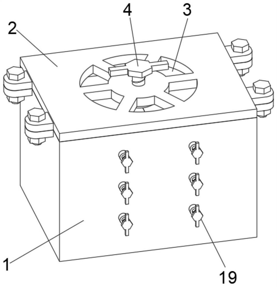
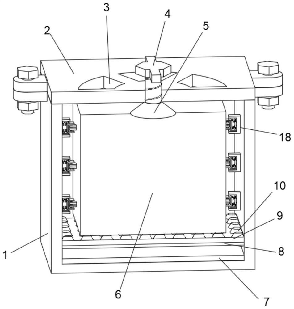
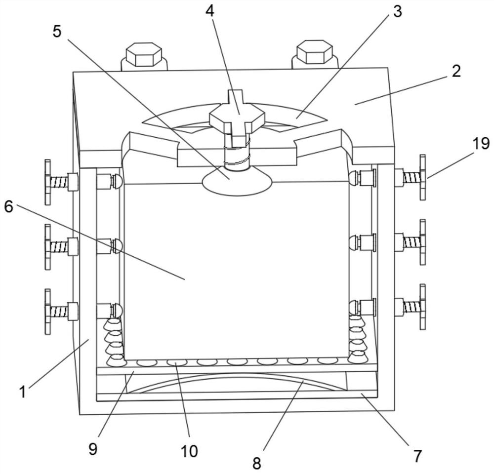
The invention discloses a battery shock absorption device of a new energy automobile, and belongs to the technical field of automobile battery shock absorption. The battery shock-proof device comprises a box body, a box cover is arranged on the upper portion of the box body, a plurality of heat dissipation openings are annularly formed in the box cover at equal intervals, an adjusting screw A is arranged in the middle of the box cover in a penetrating mode, and a suction cup is arranged at the end, penetrating through the bottom face of the box cover, of the adjusting screw A. A battery body is arranged in the box body. A buffer base is arranged on the bottom surface in the box body; An arc-shaped buffer plate is arranged on the buffer base, a supporting plate is arranged on the arc-shapedbuffer plate, and a plurality of non-slip mats are evenly arranged on the surface of the upper portion of the supporting plate. The buffer base and the arc-shaped buffer plate are arranged on the bottom surface of the box body, and the anti-skid pads are arranged at the upper parts of the support plates, so that a battery cannot shake or shift due to vibration generated in the driving process ofan automobile, and the vibration generated in the vertical direction is reduced through the spring telescopic rods arranged between the buffer base and the support plates; and the buffer mechanism isused for reducing shaking of the battery body when the vehicle body vibrates.

Description

technical field [0001] The invention relates to the technical field of automobile battery shock absorbers, and more specifically, relates to a battery shock absorber for new energy vehicles. Background technique [0002] New energy vehicles refer to vehicles that use unconventional vehicle fuel as a power source. Electric vehicles are widely used in new energy vehicles. The driving power of electric vehicles comes from on-board rechargeable batteries. When installing batteries, shock absorbers are required. It is used to buffer the collision between the battery and the battery box, but there are still some defects in the existing battery shock absorber. Generally, the shock absorber of the battery is damped by the shock absorber spring, but this shock absorber still cannot play a very good role. Good shock absorption effect, when the battery box or battery shakes, the connection of the positive and negative electrodes of the battery will be in poor contact, which will also d...

Claims


Application Information

Patent Timeline
Patent Type & Authority Applications(China)
IPC IPC(8): H01M50/242H01M50/249H01M50/289F16F15/08
CPCF16F15/085F16F2224/025F16F2238/022F16F2238/026
Inventor 唐元元李世阳唐馨徐少飞
Owner YANTAI ENG & TECH COLLEGE YANTAI TECHNICIAN INST
Why Eureka
Try Eureka