Device for treating flue gas produced during waste incineration for power generation

A technology for flue gas treatment and waste incineration, which is applied in the direction of gas treatment, separation methods, and separation of dispersed particles, etc. It can solve the problems of heat loss in the flue, difficulty in removing fly ash, and accumulation of fly ash, so as to improve efficiency and avoid cutting Effects of destroying and slowing down the flow velocity

Active Publication Date: 2021-01-29
亳州洁能电力有限公司
View PDF10 Cites 0 Cited by
  • Summary
  • Abstract
  • Description
  • Claims
  • Application Information

AI Technical Summary

Problems solved by technology

However, since the fly ash falls on the valve plate in an irregular manner, it may fall near the rotating shaft of the valve plate, resulting in a short arm of force at the position where the fly ash accumulates, and there is not enough weight to press down on the valve plate for ash discharge, which may cause Cause fly ash to accumulate on the valve plate and be difficult to remove
Some electric flap ash unloading valves open the valve plate at a fixed frequency for ash discharge, but frequent opening of the valve plate causes heat loss in the flue, but if the frequency is reduced, it may cause fly ash to accumulate

Method used


Image

  • Device for treating flue gas produced during waste incineration for power generation
  • Device for treating flue gas produced during waste incineration for power generation
  • Device for treating flue gas produced during waste incineration for power generation

Examples


Embodiment Construction

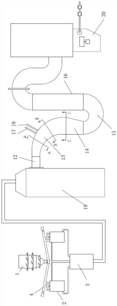
[0031] like figure 1 As shown, a waste incineration power generation flue gas treatment device of the present invention includes a flue gas semi-dry treatment device, a dry treatment device, a bag filter and an ash unloading device installed below it. The flue gas semi-dry processing device, dry processing device, and bag filter are connected in sequence.

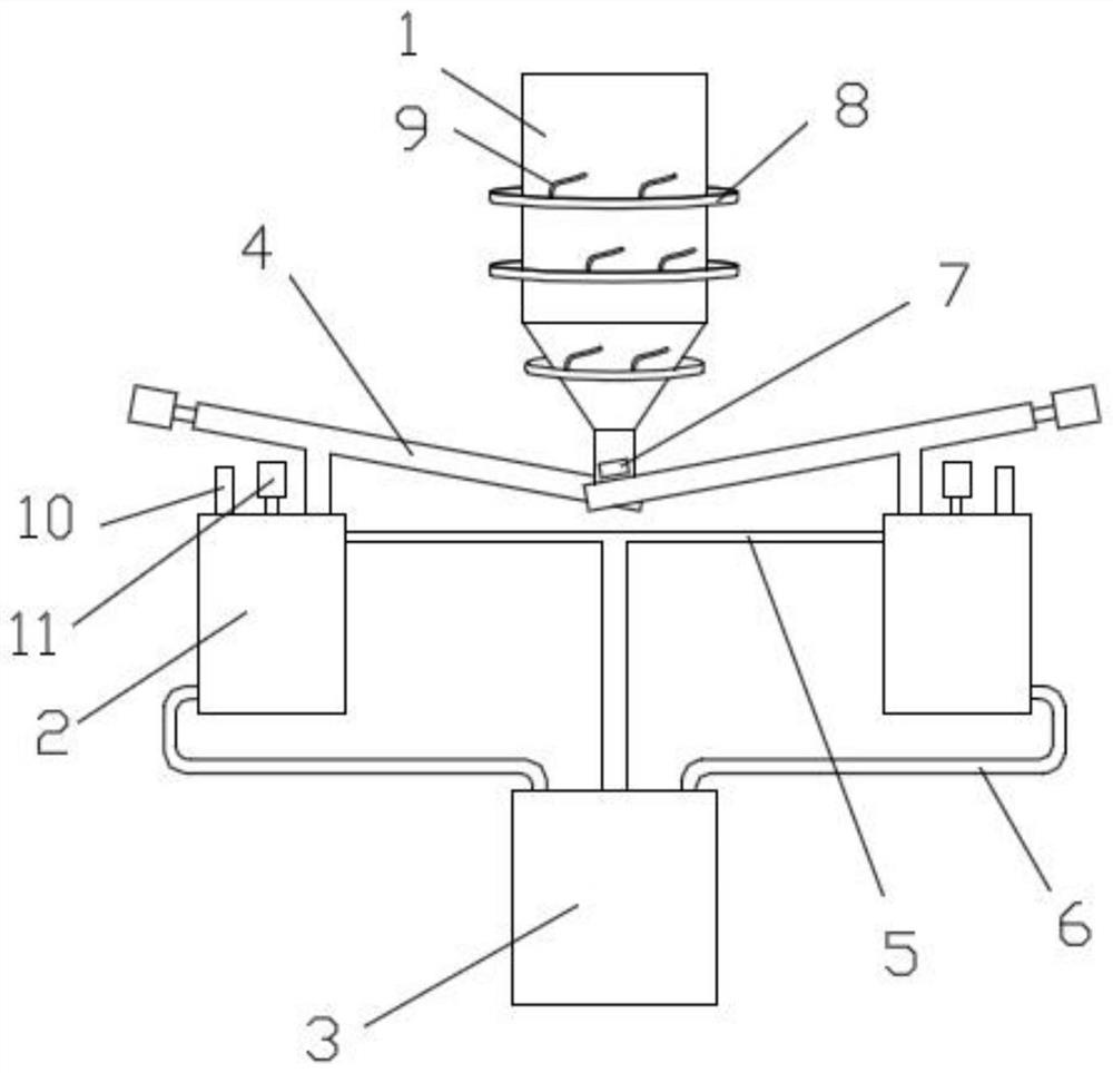
[0032] combine figure 1 , 3 As shown, the present invention is a flue gas semi-dry treatment device in a waste incineration power generation flue gas treatment device, including a slurry preparation device. The slurry preparation device includes a lime silo 1 , a lime slurry preparation tank 2 and a lime slurry storage tank 3 . A screw quantitative feeder 4 is provided at the lower part of the lime silo 1 to connect the discharge port of the lime silo and the feed inlet on the top of the lime slurry preparation tank respectively. There are multiple lime slurry preparation tanks, and correspondingly there are multiple scr...


PUM


Abstract

The invention discloses a device for treating flue gas produced during waste incineration for power generation. Flue gas generated by waste incineration for power generation sequentially passes through a flue gas semi-dry treatment device, a dry treatment device and a bag-type dust collector for treatment. A purging device is arranged on a lime bin of a slurry preparation device in the semi-dry treatment device, a plurality of lime slurry preparation tanks are arranged, a plurality of spiral constant feeders are correspondingly arranged and connected with a discharge port of the lime bin and feed ports in the tops of the lime slurry preparation tanks respectively, and a plurality of overhaul windows are formed in the lower portion of the lime bin. Due to the fact that the pipe diameters ofthe first equal-diameter circular pipe sections of the dry treatment device are consistent, flue gas flows stably, and pressure stabilizing effect is achieved; after the flue gas enters a reducing pipe expanding section, due to the fact that the pipe diameters are gradually increased, the effect of reducing a flow speed is achieved; and an oval pipe section is arranged on the reducing pipe expanding section, so flue gas treatment effect is better, and flue gas treatment efficiency is higher. Fly ash collected by the bag-type dust collector falls into an ash discharging device, and the structure can prevent the fly ash from being accumulated and fixed on a valve plate.

Description

technical field [0001] The invention relates to a waste incineration power generation flue gas treatment device, which belongs to the field of waste incineration flue gas treatment equipment. Background technique [0002] The flue gas produced in the waste incineration power generation process needs to be treated because it contains a variety of toxic and harmful substances. In the semi-dry treatment stage, lime slurry spray is used for flue gas treatment. During the preparation process of lime slurry, single-channel structure is easy to block, resulting in poor powder delivery, resulting in stoppage of pulping work and affecting flue gas treatment operations. And it is easy to attach lime powder on the lime silo inner wall that holds lime powder, causing the lime silo wall to agglomerate. The structural cross-sectional area of ​​the device in the dry treatment stage is basically unchanged, resulting in little change in the flue gas flow rate, which is not conducive to the ...

Claims


Application Information

Patent Timeline
Patent Type & Authority Applications(China)
IPC IPC(8): B01D53/75B01D53/80B01D53/83B01D53/48B01D53/10B01D46/02B01D46/48
CPCB01D53/75B01D53/80B01D53/83B01D53/48B01D53/10B01D46/02B01D46/48B01D2251/404B01D2253/102B01D2258/0291
Inventor 李腾飞汪郑正张必杰
Owner 亳州洁能电力有限公司
Why Eureka
Try Eureka