Tool for machining thin-walled disc-shaped part of aero-engine

A technology of aero-engine and parts processing

Inactive Publication Date: 2021-01-29
CHINA HANGFA GUIZHOU LIYANG AVIATION POWER CO LTD
View PDF5 Cites 10 Cited by
  • Summary
  • Abstract
  • Description
  • Claims
  • Application Information

AI Technical Summary

Problems solved by technology

[0002] As a typical component in the manufacturing process of aero-engines, aero-engine fan disc-shaped parts require high processing accuracy. The clamping and positioning methods commonly used in general machining often cannot meet their requirements. It takes time and effort for the staff to process. It is also difficult to get a good guarantee. Therefore, it is urgent to provide a tooling for positioning, supporting and pressing the thin-walled disc-shaped parts of the aero-engine, to improve the clamping accuracy, reduce the processing error, and improve the processing efficiency of the product.

Method used


Image

  • Tool for machining thin-walled disc-shaped part of aero-engine
  • Tool for machining thin-walled disc-shaped part of aero-engine
  • Tool for machining thin-walled disc-shaped part of aero-engine

Examples


Embodiment Construction

[0029] The technical solution of the present invention is further described below, but the scope of protection is not limited to the description.

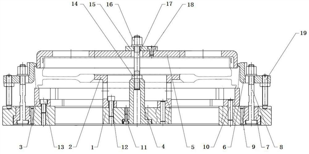
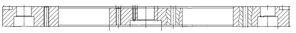
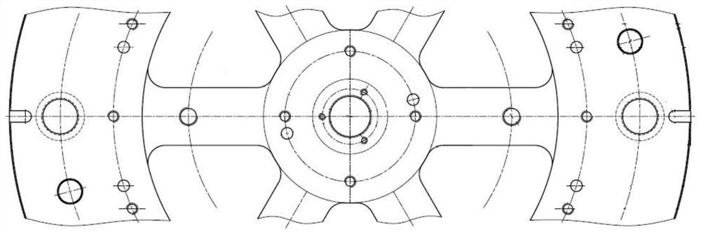
[0030] Such as Figure 1-9 As shown, a tooling for processing thin-walled disc-shaped parts of aero-engines according to the present invention includes a C-shaped circular base 1, a positioning ring 2, a support block 3, a shaft 4, a gland 5, a pressure plate 6, a lining Cover 7, bolt 8, second screw 12, third screw 13, second nut 16, stud 17;

[0031] The C-shaped circular base 1 is a ring-shaped hollow structure in the middle, with mounting threaded holes in the middle, and six evenly distributed countersunk threaded holes on the peripheral annular support surface. The purpose of the countersunk holes is to insert bolts. 8. The C-shaped circular base 1 is connected with the machine tool;

[0032] The locating ring 2 is hollow and annular, and its outer diameter is compatible with the diameter of the inner ring of the part to be...


PUM


Abstract

The invention discloses a tool for machining a thin-walled disc-shaped part of an aero-engine. The tool mainly comprises a C-shaped circular base, a positioning ring, a support block, a shaft, a gland, a pressing plate, bushes, bolts, second screws, third screws, a second nut and a stud. Inner hole positioning of a to-be-machined part is formed after the part is connected, so that clamping precision is guaranteed; meanwhile, when the interior of the part is turned, the gland can be removed and the pressing plate can be installed; when the excircle of the part is turned, the gland can be installed and the pressing plate can be removed; and the same clamp can be applied to two machining procedures, so that the machining precision of the part is guaranteed, and the manufacturing cost of the part clamp is reduced.

Description

technical field [0001] The invention belongs to the manufacturing technology of aero-engines, in particular to a tool for processing thin-walled disc-shaped parts of aero-engines. Background technique [0002] As a typical component in the manufacturing process of aero-engines, aero-engine fan disc-shaped parts require high processing accuracy. The clamping and positioning methods commonly used in general machining often cannot meet their requirements. It takes time and effort for the staff to process. It is also difficult to get a good guarantee. Therefore, it is urgent to provide a tooling for positioning, supporting and pressing thin-walled disc-shaped parts of aero-engines to improve clamping accuracy, reduce processing errors, and improve product processing efficiency. Contents of the invention [0003] In order to solve the above technical problems, the present invention provides a tool for machining thin-walled disc-shaped parts of aero-engines. [0004] The presen...

Claims


Application Information

Patent Timeline
Patent Type & Authority Applications(China)
IPC IPC(8): B23Q3/06
CPCB23Q3/062
Inventor 惠畅何绍川熊勇
Owner CHINA HANGFA GUIZHOU LIYANG AVIATION POWER CO LTD
Why Eureka
Try Eureka