Power assembly suspension structure for light commercial vehicle and assembling method of power assembly suspension structure
A technology for powertrains and commercial vehicles, applied in the direction of power units, substructures, vehicle components, etc., can solve problems such as time-consuming and low efficiency, achieve time-saving and labor-saving assembly, improve assembly efficiency, and provide good positioning and guidance The effect of action
- Summary
- Abstract
- Description
- Claims
- Application Information
AI Technical Summary
Problems solved by technology
Method used
Image
Examples
Embodiment 1
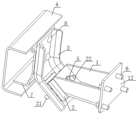
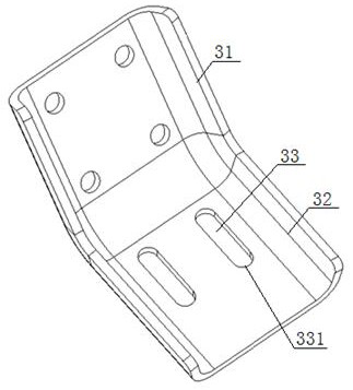
[0037] see figure 1 , figure 2 , a powertrain suspension structure for a light commercial vehicle, comprising a suspension bracket 1, a suspension cushion assembly 2, and a suspension bracket 3, the two sides of the suspension bracket 1 are respectively connected to the powertrain, the suspension The upper frame of the suspension cushion assembly 2 is fixedly connected, and the bottom surface of the lower skeleton of the suspension cushion assembly 2 is provided with two fixing bolts 21. The suspension bracket 3 is a V-shaped plate structure, including a The No. 1 connecting plate 31 and the No. 2 connecting plate 32. The No. 1 connecting plate 31 is fixedly connected to the frame longitudinal beam 4 through the frame reinforcement plate 7. The upper end of the No. 2 connecting plate 32 is connected to the lower end of the No. 1 connecting plate 31. Fixedly connected, the middle part of the No. 2 connecting plate 32 is fixedly connected with the fixing bolts 21 one by one th...
Embodiment 2
[0040] Structure is the same as embodiment 1, and difference is:
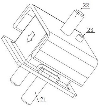
[0041] see image 3 , Figure 4, the suspension bracket 1 is a box-shaped structure, the No. 1 side plate 11 of the suspension bracket 1 is provided with a positioning hole 111 and a mounting hole 112, and the top surface of the upper skeleton of the suspension cushion assembly 2 is provided with Mounting bolt 22, locating pin 23, described mounting bolt 22 passes through mounting hole 112 and is fixed by flange surface nut 5, and described locating pin 23 is inserted and matched with locating hole 111, and the diameter of described locating hole 111, locating pin 23 The section is circular, the length of the positioning pin 23 is 2-3mm larger than the depth of the positioning hole 111, and the outer diameter of the positioning pin 23 is 0.5-1mm smaller than the inner diameter of the positioning hole 111. The head of the positioning pin 23 It is a truncated conical structure with a height of 0.5-1 mm. The No....
PUM
 Abstract
Description
Claims
Application Information
 - R&D
- Intellectual Property
- Life Sciences
- Materials
- Tech Scout
- Unparalleled Data Quality
- Higher Quality Content
- 60% Fewer Hallucinations
Browse by: Latest US Patents, China's latest patents, Technical Efficacy Thesaurus, Application Domain, Technology Topic, Popular Technical Reports.
© 2025 PatSnap. All rights reserved.Legal|Privacy policy|Modern Slavery Act Transparency Statement|Sitemap|About US| Contact US: help@patsnap.com


