A supercharged thermal vaporization phase change consolidation method and its thermal desensitization batch evaporator
An intermittent, evaporator technology, applied in vertical tube evaporators, evaporation, steam generation, etc., can solve the problems that the structure of the heating device cannot achieve intermittent heating and low heating efficiency, and achieve accelerated phase transition consolidation and improved foundation. The effect of carrying capacity and reducing investment cost
- Summary
- Abstract
- Description
- Claims
- Application Information
AI Technical Summary
Problems solved by technology
Method used
Image

Examples
Embodiment 1
[0043] Example 1: A pressurized heat-sensitive gasification consolidation method, combined with the method of pressurized vacuum precompression consolidation treatment of soft soil foundation (ZL200810156787.5) and the sludge consolidation drainage plate and filter cloth and drainage plate core ( ZL200910181702.3), including the following steps:
[0044] S1. Place the thermally desensitized batch evaporator in the bottom area of the vacuum pre-pressed drainage plate in the sludge reinforcement area, turn on the heating, and spray high-pressure steam from the thermally desensitized batch evaporator during heating;
[0045] S2. Heating to 200°C, maintaining for 6min, then stopping for 12min,
[0046] The vacuum pressure is 90kPa, and the above process is repeated;
[0047] S3. When the liquid limit index of the surrounding reinforced soil is less than 0.98, the heating is stopped, and the gasification and consolidation are completed.
[0048] With reference to Example 1, Exa...
Embodiment 6
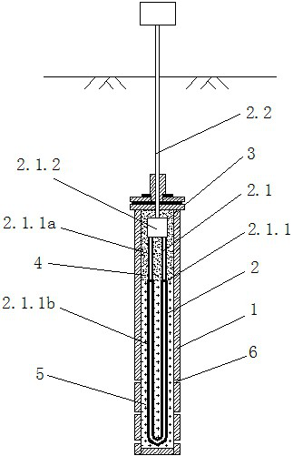
[0050] Example 6: as figure 1 As shown in the figure, a thermally desensitized batch evaporator for pressurized heat-sensitive gasification and consolidation method comprises a casing 1, two heating bodies 2 placed in the casing 1, and the heating body 2 comprises an electric heating body 2.1 and The wire 2.2 connected to the electric heating body 2.1, the wire 2.2 leads out of the housing 1 to connect to the power supply, the electric heating body 2.1 includes the heating tube base 2.1.1 and the metal joint 2.1.2 installed on the top of the heating tube base 2.1.1, the metal joint 2.1. 2 Connecting wires 2.2, heating tube base 2.1.1 includes upper and lower bases 2.1.1a and 2.1.1b, upper base 2.1.1a is graphite, lower base 2.1.1b is quartz, upper base 2.1.1a and metal joint 2.1. 1 Connection, the entire heating tube base 2.1.1 is formed by pressing and sintering of quartz and graphite abrasives, the metal joint 2.1.2 of the heating tube base 2.1.1 is wrapped with high tempera...
Embodiment 7
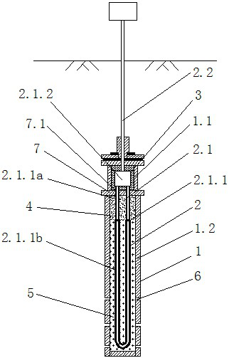
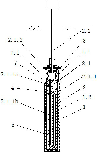
[0051] Example 7: as figure 2 As shown, referring to Embodiment 6, the housing 1 is divided into upper and lower parts 1.1 and 1.2, and a partition 7 is arranged in the middle, and the partition 7 is provided with an insertion hole 7.1, and the heating tube base 2.1.1 is inserted into the insertion hole 7.1. The connection hole 7.1 is fixed inside, and the metal joint 2.1.2 is located in the upper part of the shell 1.1. Effectively prevent the heating tube substrate from being displaced and broken in the shell, and easily broken due to the strong rigidity of the refractory material.
PUM
 Abstract
Description
Claims
Application Information
 - R&D
- Intellectual Property
- Life Sciences
- Materials
- Tech Scout
- Unparalleled Data Quality
- Higher Quality Content
- 60% Fewer Hallucinations
Browse by: Latest US Patents, China's latest patents, Technical Efficacy Thesaurus, Application Domain, Technology Topic, Popular Technical Reports.
© 2025 PatSnap. All rights reserved.Legal|Privacy policy|Modern Slavery Act Transparency Statement|Sitemap|About US| Contact US: help@patsnap.com