Core tube flange closed section column joint with self-tapping bolts and construction method of core tube flange closed section column joint

A column node and core tube technology, which is applied in the processing of building materials, construction, building structure, etc., can solve the problems that the connection nodes of all-bolt columns cannot be rigidly connected, the construction process is complicated, and the construction efficiency is low. Simple, improve construction progress, and facilitate disassembly and assembly

Inactive Publication Date: 2021-01-29
BEIJING UNIVERSITY OF CIVIL ENGINEERING AND ARCHITECTURE
View PDF8 Cites 2 Cited by
  • Summary
  • Abstract
  • Description
  • Claims
  • Application Information

AI Technical Summary

Problems solved by technology

It aims to solve the problems of complex construction process, low construction efficiency, poor seismic performance, and rigid connection of full-bolt column connection nodes in the prior art.

Method used


Image

  • Core tube flange closed section column joint with self-tapping bolts and construction method of core tube flange closed section column joint
  • Core tube flange closed section column joint with self-tapping bolts and construction method of core tube flange closed section column joint
  • Core tube flange closed section column joint with self-tapping bolts and construction method of core tube flange closed section column joint

Examples


Embodiment Construction

[0029] Embodiments of the present invention will be further described in detail below in conjunction with the accompanying drawings and examples. The following examples are used to illustrate the present invention, but should not be used to limit the scope of the present invention.

[0030] In the description of the present invention, unless otherwise specified, "plurality" means two or more; unless otherwise specified. The orientation or positional relationship indicated by the terms "upper", "lower", "left", "right", "inner", "outer", "front end", "rear end", "head", "tail" etc. is Based on the orientation or positional relationship shown in the drawings, it is only for the convenience of describing the present invention and simplifying the description, and does not indicate or imply that the referred device or element must have a specific orientation, be constructed and operated in a specific orientation, and therefore cannot be understood To limit the present invention. ...


PUM


Abstract

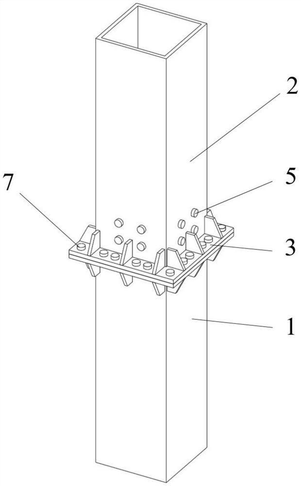
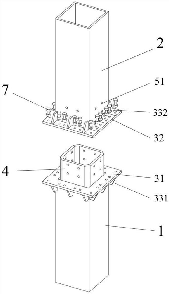
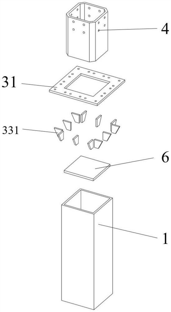
The invention relates to the technical field of civil engineering, and particularly discloses a core tube flange closed section column joint with self-tapping bolts and a construction method of the core tube flange closed section column joint. The core tube flange closed section column joint comprises a lower-layer steel column and an upper-layer steel column, a flange plate is arranged between the upper-layer steel column and the lower-layer steel column, and the upper-layer steel column is detachably connected with the lower-layer steel column through the flange plate; a core tube is arranged in the lower-layer steel column and connected with the lower-layer steel column through welding, and the upper part of the core tube is embedded in the upper-layer steel column; self-tapping bolt holes are formed in the four side column walls of the bottom end of the upper-layer steel column at intervals, self-tapping bolt holes are further formed in the upper part of the core tube, and the coretube is connected with the upper-layer steel column through the self-tapping bolts; and partition plates are arranged inside the lower-layer steel column and at the bottom end of the core tube, and the partition plates make close contact with the inner wall of the lower-layer steel column and are fixedly connected with the inner wall of the lower-layer steel column. The joint domain rigidity canbe effectively enhanced, and safety and reliability are achieved; the structure is simple and assembling is rapid; and the problems that a traditional full-penetration welding joint is low in field welding construction efficiency, poor in welding quality and the like are solved, and the construction efficiency is greatly improved.

Description

technical field [0001] The invention relates to the technical field of civil engineering, in particular to the technical field of core tube flange closed section column joints. Background technique [0002] Column connection joints are the key to the design of prefabricated steel structures, which determine the construction progress and degree of assembly of the overall structure. However, the current full penetration welding joints of box columns have the following problems: low efficiency of on-site welding construction, difficulty in on-site welding quality Guarantee, under the action of the earthquake, due to the influence of welding stress, the damage is serious, the durability is poor, the environmental pollution is serious, and the structural detachability is poor. At present, in the field of civil engineering, there are two types of connection nodes of closed-section columns: flange connection nodes of closed-section columns and sleeve connection nodes of closed-sect...

Claims


Application Information

Patent Timeline
IPC IPC(8): E04B1/24E04B1/58E04G21/14
CPCE04B1/24E04B1/2403E04B1/58E04B2001/2406E04B2001/2466E04G21/14
Inventor 张爱林张艳霞上官广浩吴浩
Owner BEIJING UNIVERSITY OF CIVIL ENGINEERING AND ARCHITECTURE
Why Eureka
Try Eureka