
Direct air cooling unit cold end dead steam waste heat utilization system combined with absorption heat pump

An absorption heat pump and air-cooling unit technology, applied in heat pumps, refrigerators, refrigeration components, etc., can solve the problems of lower comprehensive utilization of energy, loss of waste heat from exhausted steam, and inability to effectively recycle waste heat from exhausted steam, etc. load capacity, reduce cold source loss, and reduce the effect of grid assessment pressure

Pending Publication Date: 2021-01-29
NORTHWEST BRANCH OF CHINA DATANG CORP SCI & TECH RES INST
View PDF0 Cites 0 Cited by
  • Summary
  • Abstract
  • Description
  • Claims
  • Application Information

AI Technical Summary

Problems solved by technology

[0004] The purpose of the present invention is to provide a direct air-cooling unit cold-end exhaust steam waste heat utilization system combined with an absorption heat pump, which solves the problem that the exhaust steam waste heat in the prior art cannot be effectively recycled, and the loss of exhaust steam waste heat causes comprehensive utilization of energy. Drastically reduces the problem

Method used


Image

  • Direct air cooling unit cold end dead steam waste heat utilization system combined with absorption heat pump

Examples


Embodiment Construction

[0019] The present invention will be described in detail below in conjunction with the accompanying drawings and specific embodiments.

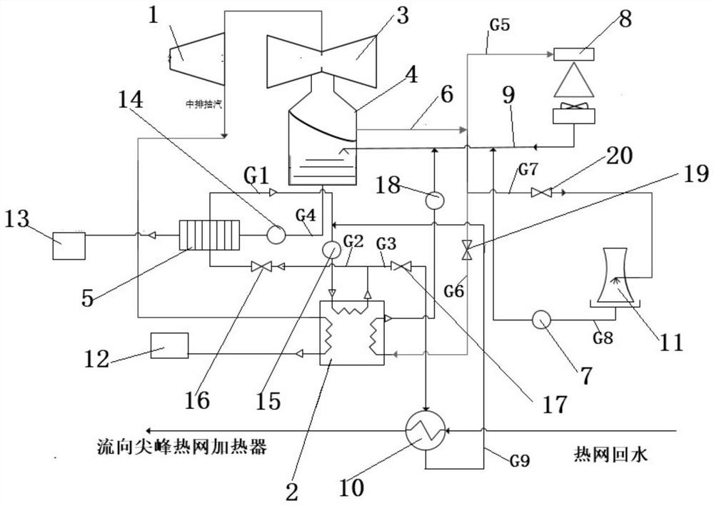
[0020] The present invention combines the absorption heat pump with the direct air-cooling unit cold-end exhaust steam waste heat utilization system, and its structure is as follows figure 1 As shown, it includes the medium-pressure cylinder 1 of the steam turbine, the exhaust port of the medium-pressure cylinder 1 of the steam turbine is respectively connected with the absorption heat pump 2 and the low-pressure cylinder 3 of the steam turbine through pipelines, and the steam exhaust device 4 is arranged under the low-pressure cylinder 3 of the steam turbine, and the steam exhaust device 4 The bottom is connected with a heat exchanger 5 through a pipeline, and the heat exchanger 5 and the absorption heat pump 2 form a circulation loop through a pipeline. An exhaust pipeline 6 is connected above the side wall of the exhaust device 4, and the o...


PUM


Abstract

The invention discloses a direct air cooling unit cold end dead steam waste heat utilization system combined with an absorption heat pump, the direct air cooling unit cold end dead steam waste heat utilization system comprises a turbine medium-pressure cylinder, the turbine medium-pressure cylinder is respectively connected with the absorption heat pump and a turbine low-pressure cylinder throughpipelines, a steam exhaust device is arranged below the turbine low-pressure cylinder, and the bottom of the steam exhaust device is connected with a heat exchanger. The heat exchanger and the absorption heat pump form a circulation loop through a pipeline, the side wall of the steam exhaust device is connected with a steam exhaust pipeline, the other end of the steam exhaust pipeline is connectedwith an air cooling island, the absorption heat pump and a mechanical ventilation tower, and the air cooling island is connected with the steam exhaust device through a condensate pipe. The absorption heat pump is connected with the condensate pipe through a pipeline. The absorption heat pump is further connected with a heating network heater through a pipeline to form a circulation loop, the heating network heater is further connected with the heat exchanger through a pipeline, and the mechanical ventilation tower is further connected with the condensate pipe through a pipeline. The problemsthat in the prior art, dead steam waste heat cannot be effectively recycled, and the comprehensive utilization rate of energy is greatly reduced due to dead steam waste heat loss are solved.

Description

technical field [0001] The invention belongs to the technical field of thermal power generation, and relates to a direct air-cooling unit cold end exhaust steam waste heat utilization system combined with an absorption heat pump. Background technique [0002] The proportion of thermal power in the energy ratio is still the first, and the air-cooled unit accounts for more than 20% of the thermal power unit. The advantage of water saving makes it widely built in the arid and water-scarce areas of Northwest my country, becoming the power source for these areas. pillar. Air-cooled units are mainly divided into two categories, direct air-cooled and indirect air-cooled. Both types of air-cooled units will eventually release heat to the air, so the air-cooled units are strongly affected by environmental conditions. Due to the large range of temperature changes throughout the year in the area where the direct air cooling unit is located, the extreme cold in winter and the high temp...

Claims


Application Information

Patent Timeline
IPC IPC(8): F22D1/50F25B30/04F25B30/06F28B1/06F28B9/08
CPCF22D1/50F25B30/04F25B30/06F28B1/06F28B9/08
Inventor 薛康康
Owner NORTHWEST BRANCH OF CHINA DATANG CORP SCI & TECH RES INST
Learn More