A steam injector and its structural optimization method

An optimization method and injector technology, applied in jet pumps, design optimization/simulation, machines/engines, etc., can solve the problems of low steam turbine exhaust pressure, heat loss, environmental pollution, etc., achieve high thermal efficiency and reduce plant power consumption Reasonable design of efficiency and structure size

Active Publication Date: 2022-04-19
INNER MONGOLIA UNIV OF TECH
View PDF0 Cites 0 Cited by
  • Summary
  • Abstract
  • Description
  • Claims
  • Application Information

AI Technical Summary

Problems solved by technology

However, the direct discharge of exhaust steam from steam turbines in thermal power plants has caused environmental pollution and serious heat loss, but the exhaust steam of steam turbines has low pressure and low heat and cannot be directly used for heating

Method used


Image

  • A steam injector and its structural optimization method
  • A steam injector and its structural optimization method
  • A steam injector and its structural optimization method

Examples


Embodiment 1

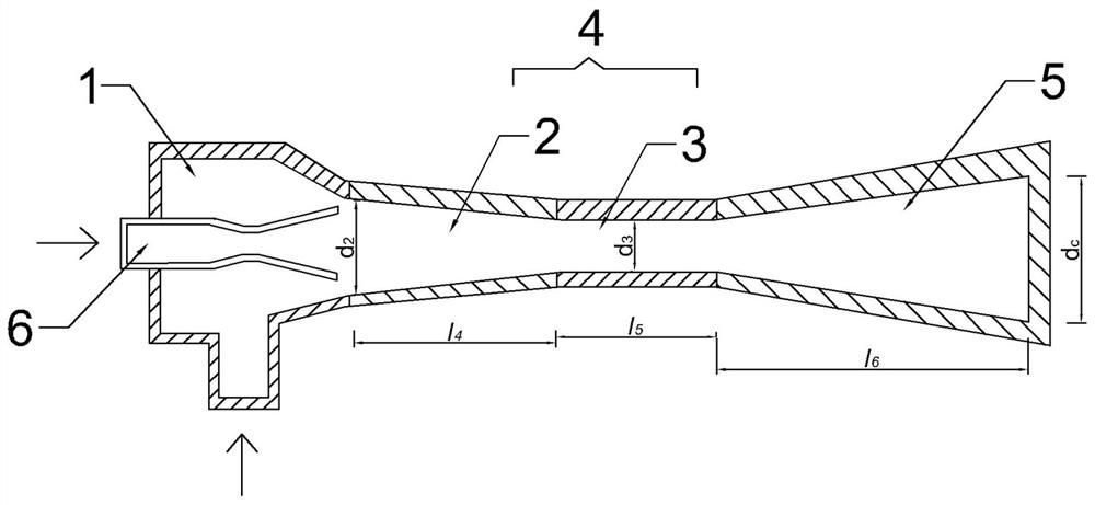
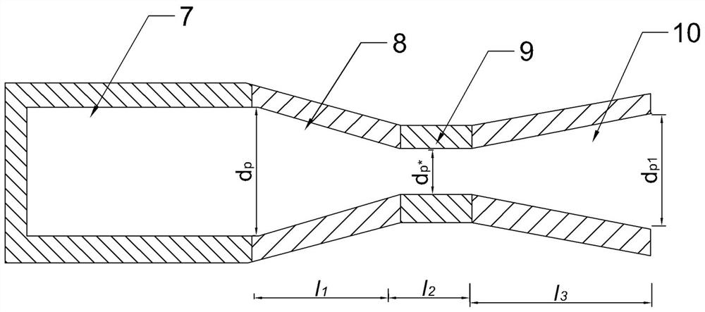
[0055] like figure 1 and 2 As shown, a steam ejector includes a receiving chamber 1 communicated with each other, a mixing chamber 4, a diffuser chamber 5, and a nozzle 6 arranged at the entrance of the receiving chamber 1. Air inlet; the mixing chamber 4 includes a converging section 2 and a transition section 3, and the nozzle 6 includes an inlet section 7, a converging section 8, a throat section 9 and an expansion section 10; the transition section 3 and the throat section 9 is a hollow cylinder.

[0056] The structure optimization method of the steam injector, for the nozzle throat section diameter x 1 , the diameter of the end of the expansion section x 2 , the diameter of the transition section x 3 , the shrinkage section length of the mixing chamber x 4 and transition length x 5 Five structural parameters were optimized. Include the following steps:

[0057] (1) CFD numerical simulation:

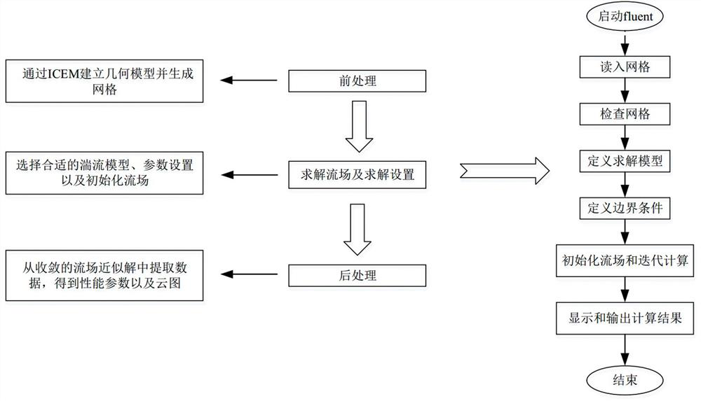
[0058] like image 3 As shown, the CFD numerical simulation process is...

Embodiment 2

[0110] A steam ejector, comprising a receiving chamber 1, a mixing chamber 4, a diffuser chamber 5 communicated with each other, and a nozzle 6 arranged at the entrance of the receiving chamber 1, and an air inlet is arranged below the receiving chamber 1 The mixing chamber 4 includes a constriction section 2 and a transition section 3, and the nozzle 6 includes an inlet section 7, a tapering section 8, a throat section 9 and an expansion section 10; the transition section 3 and the throat section 9 are hollow Cylindrical.

[0111] The diameter of the inlet section 7 of the nozzle 6 is d p 130mm, its throat section 9 diameter d p* is 31.34mm, and the end diameter of the expansion section 10 is d p1 is 80.52mm; the diameter of the beginning end of the constriction section 2 of the mixing chamber 4 is d 2 is 220mm, the diameter d of the transition section 3 3 It is 179.14mm.

[0112] The tapered section 8 length l of the nozzle 6 1 is 101mm, and its throat section 9 has a ...


PUM


Abstract

The invention discloses a steam injector, which comprises a receiving chamber, a mixing chamber, a diffuser chamber communicated with each other, and a nozzle arranged at the entrance of the receiving chamber, and an air inlet is arranged under the receiving chamber; The mixing chamber includes a constriction section and a transition section, and the nozzle includes an inlet section, a constriction section, a throat section and an expansion section; the transition section and the throat section are in the shape of a hollow cylinder. Also disclosed is a structural optimization method of the steam injector, including CFD numerical simulation, establishment of an objective function model and structural optimization calculation. The optimized steam ejector of the invention has good performance coefficient, less gas consumption, reasonable sum, minimum volume and low operation cost.

Description

technical field [0001] The invention relates to the technical field of steam injectors, in particular to a steam injector and a structure optimization method thereof. Background technique [0002] The steam in the steam turbine is needed for heating in winter, and the adjustment of steam affects the amount of steam required for power supply, which may easily cause insufficient power generation. Now, the method of limiting power consumption is usually used to solve the power consumption pressure. The direct discharge of exhaust steam from steam turbines in thermal power plants has caused environmental pollution and serious heat loss, but the exhaust steam of steam turbines has low pressure and low heat and cannot be directly used for heating. [0003] Therefore, it is necessary to design a method to convert low-temperature and low-pressure steam into medium-temperature and medium-pressure steam, so as to solve the problem of power generation and heating in thermal power plant...

Claims


Application Information

Patent Timeline
Patent Type & Authority Patents(China)
IPC IPC(8): F04F5/16F04F5/46F04F5/44G06F30/17G06F30/28
CPCF04F5/16F04F5/46F04F5/44G06F30/17G06F30/28
Inventor 胡林静王志艳席东民
Owner INNER MONGOLIA UNIV OF TECH
Why Eureka
Try Eureka