Gradient utilization method and device of boiler flue gas waste heat

A boiler flue gas and waste heat technology, which is applied in the directions of preheating, feed water heater, lighting and heating equipment, etc., can solve the problems such as failure to achieve temperature matching, cascade utilization, small contribution to unit power generation, and reduction of flue gas temperature, etc. Achieve the effect of realizing heat utilization, large cooling range and increasing air temperature

Inactive Publication Date: 2015-03-18
JINAN HIPOWER TECH
View PDF0 Cites 4 Cited by
  • Summary
  • Abstract
  • Description
  • Claims
  • Application Information

AI Technical Summary

Problems solved by technology

However, there is a limit to reducing the exhaust gas temperature. On the one hand, when the exhaust gas temperature is relatively low, as the temperature of the flue gas further decreases, the temperature difference with the air decreases, that is, the heat transfer area of ​​the air preheater increases a lot, and the temperature of the flue gas decreases. On the other hand, when the exhaust gas temperature is low and the wall temperature of the preheater tube is lower than the dew point of the flue gas, low-temperature corrosion will occur, and the preheater will need to be replac...

Method used


Image

  • Gradient utilization method and device of boiler flue gas waste heat

Examples


Embodiment 1

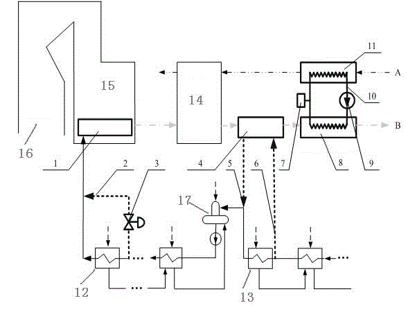
[0032] of the present invention Boiler flue gas waste heat cascade utilization device , an additional heating surface 1 is added to the economizer 15 section of the boiler 16 of the thermal power unit, and a bypass pipe 2 is set at the feeder pipe at the inlet of the last stage high-pressure heater 12 on the steam turbine side to lead to the feeder pipe at its outlet, and the bypass pipe A flow regulating valve 3 is provided on it.

Embodiment 2

[0034] Between the air preheater 14 and the flue gas-oil heat exchanger 8, a low-heat heat exchanger 4 for heat exchange between hot flue gas and water is provided; a water diversion pipe 6 is provided on the water inlet side of the last low-pressure heater 13 Leading to the low heating heat exchanger, the water inlet pipe 5 from the low heating heat exchanger is added on the water inlet side of the deaerator 17.

Embodiment 3

[0036] of the present invention Boiler flue gas waste heat cascade utilization device , an additional heating surface 1 is added to the economizer 15 section of the boiler 16 of the thermal power unit, and a bypass pipe 2 is set at the feeder pipe at the inlet of the last stage high-pressure heater 12 on the steam turbine side to lead to the feeder pipe at its outlet, and the bypass pipe A flow regulating valve 3 is provided on it.

[0037]A flue gas-oil heat exchanger 8 and an air-oil heat exchanger 11 are added at the cold end of the air preheater, and a circulation pipeline 10 is provided between the flue gas-oil heat exchanger 8 and the air-oil heat exchanger 11, The heat transfer medium and heat transfer oil are injected into the circulation pipeline. The expansion tank 7 and the circulation pump 9 are installed on the circulation pipeline. One end of the flue gas-oil heat exchanger is connected with the smoke outlet of the air preheater, and the other end is equipped wi...


PUM


Abstract

The invention discloses a gradient utilization method and device of boiler flue gas waste heat. An additional heating face is added to an economizer segment of a boiler of a thermal power generating unit; a bypass pipe is provided at a water feed main arranged at an inlet of a steam turbine side high-pressure heater and leads to another water feed main arranged at an outlet of the steam turbine side high-pressure heater; the bypass pipe is provided with a flow regulating valve; a flue gas-oil heat exchanger and an air-oil heat changer are added to the cold end of an air preheater; a circulating pipeline is provided between the flue gas-oil heat exchanger and the air-oil heat changer; the circulating pipeline is filled with heat transfer medium, heat transfer oil; the circulating pipeline is provided with an expansion tank and a circulating pump; a low-pressure heat exchanger is disposed between the air preheater and the flue gas-oil heat exchanger; the inflow side of a low-pressure heater is provided a guide pipe leading to the low-pressure heat exchanger; an inflow pipe from the low-pressure heat exchanger is added to the inflow side of an oxygen extractor. The gradient utilization method and device of boiler flue gas waste heat has the advantages that suited gradient utilization of flue gas waste heat is achieved, boiler efficiency and generating efficiency of the thermal power generating unit are improved, energy consumption of the thermal power generating unit is lowered, and emission of carbon dioxide is reduced.

Description

technical field [0001] The invention relates to a method and a device for cascaded utilization of waste heat of boiler flue gas, which can reduce the exhaust gas temperature of a thermal power unit, improve the thermal efficiency of the boiler and the power generation efficiency of the unit, reduce coal consumption for power generation, and reduce pollution discharge. Background technique [0002] In the boiler heat loss, the power plant exhaust heat loss accounts for a large proportion. For every 10~15°C reduction in exhaust gas temperature, the boiler efficiency can be increased by 1%. At present, the design exhaust gas temperature of large-scale units is generally 120~130°C. With the continuous improvement of flue gas desulfurization and denitrification technology, the acid dew point of flue gas is around 90°C, so there is still a lot of room for the exhaust gas temperature to decrease. At the same time, the exhaust gas temperature of supercritical and ultra-supercritica...

Claims


Application Information

Patent Timeline
IPC IPC(8): F22D1/36
Inventor 向文国王伟田鹏李硕
Owner JINAN HIPOWER TECH
Why Eureka
Try Eureka