Device and method for compressing air and flue gas in oxygen-rich combustion system and recycling residual heat

A technology of oxygen-enriched combustion and waste heat recovery, applied in chemical instruments and methods, combined devices, separation methods, etc., can solve problems such as national economic loss and efficiency decline, and achieve the goal of reducing steam extraction, improving service life, and improving system efficiency. Effect

Active Publication Date: 2019-01-01
SOUTHEAST UNIV
View PDF9 Cites 4 Cited by
  • Summary
  • Abstract
  • Description
  • Claims
  • Application Information

AI Technical Summary

Problems solved by technology

However, the two modules of air separation and flue gas treatment have reduced the efficiency of the entire system by about 10%. With the advancement of science and technology, the demand for energy in human life, industry, and commercial activities is increasing. It will cause huge losses to the national economy, so waste heat recovery is an effective means to improve oxygen-enriched combustion technology and has great economic benefits

Method used


Image

  • Device and method for compressing air and flue gas in oxygen-rich combustion system and recycling residual heat
  • Device and method for compressing air and flue gas in oxygen-rich combustion system and recycling residual heat
  • Device and method for compressing air and flue gas in oxygen-rich combustion system and recycling residual heat

Examples


Embodiment 1

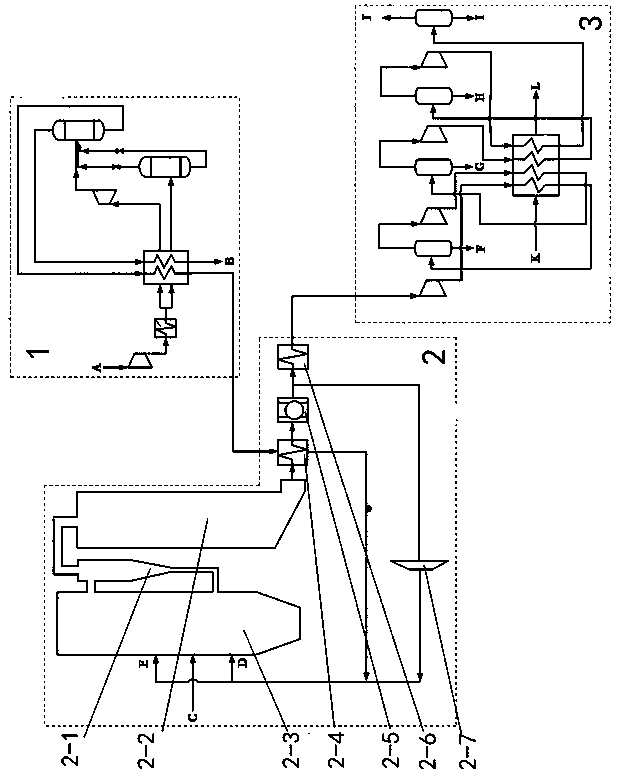
[0029] Embodiment 1: as figure 1 The shown device for air and flue gas compression and waste heat recovery in an oxyfuel combustion system includes an air separation unit 1, a circulating fluidized bed boiler unit 2, and a carbon dioxide compression and purification unit 3; the circulating fluidized bed boiler unit 2 includes : Fluidized bed furnace 2-3, cyclone separator 2-1, tail convection flue 2-2, oxygen preheater 2-4, flue gas dust collector 2-5, flue gas water supply heat exchanger 2-6 and Circulating fan 2-7; the fluidized bed furnace 2-2 is provided with a coal feed port C, a primary air inlet D, and a secondary air inlet E, and the fluidized bed furnace 2-3 passes through the cyclone separator 2-1 Connect the tail convection flue 2-2, and the end of the tail convection flue 2-2 is sequentially connected to the heat exchange tube of the oxygen preheater 2-4, the flue gas dust collector 2-5 and the flue gas water supply heat exchanger 2 through pipelines -6, the end o...

Embodiment 2

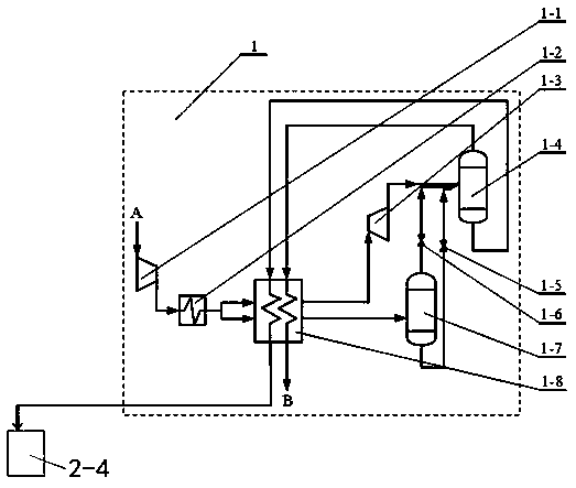
[0030] Embodiment 2: as figure 2 As shown, the air separation assembly 1 includes an air compressor 1-1, an air-to-water heat exchanger 1-2, an air cooler 1-8, an air turbine 1-3, a first throttle valve 1-6, a second section Stream valve 1-5, upper rectification tower 1-4 and lower rectification tower 1-7; Described air compressor 1-1 connects the heating pipe of air cooler 1-8 through air-to-water heat exchanger 1-2 The heating pipeline of the air cooler 1-8 is respectively connected to the air turbine 1-3 and the lower rectification tower 1-7 through two air pipes, and the upper and lower ends of the lower rectification tower 1-7 are respectively provided with first Throttle valve 1-6 and second throttle valve 1-5, air turbine 1-3, first throttle valve 1-6 and second throttle valve 1-5 are all connected to upper rectifying column 1-4 The upper and lower ends of the upper rectifying tower 1-4 are connected to the heat exchange pipeline of the air cooler 1-8, and the heat exch...

Embodiment 3

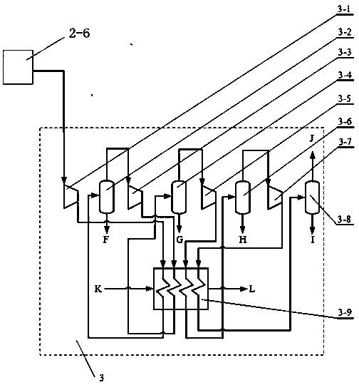
[0031] Embodiment 3: as image 3 As shown, the carbon dioxide compression and purification assembly 3 is composed of a carbon dioxide feed water heat exchanger 3-9 and a multi-stage compression dehydration unit, and each stage compression dehydration unit is composed of a single carbon dioxide compressor 3-1, 3-3, 3-5, 3-7 and a single carbon dioxide dehydration device 3-2, 3-4, 3-6, 3-8; the flue gas feed water heat exchanger 2-6 is connected to the carbon dioxide compressor of the first stage compression dehydration unit On the air inlet of 3-1, the carbon dioxide compressor 3-1 is connected to the carbon dioxide dehydration device 3-2 through the carbon dioxide water supply heat exchanger 3-9, and the bottom of the carbon dioxide dehydration device 3-2, 3-4, 3-6, 3-8 Condensed water outlets F, G, H, I are provided, and the top of the carbon dioxide dehydration device 3-2 is connected to the inlet port 3-3 of the carbon dioxide compressor of the next-stage compression dehydr...


PUM


Abstract

The invention discloses a device and a method for compressing air and flue gas in an oxygen-rich combustion system and recycling residual heat. The device comprises an air separation assembly, a circulating fluidized bed boiler assembly and a carbon dioxide compression and purification assembly. According to the device disclosed by the invention, high-purity oxygen and coal are combusted in a hearth of a fluidized bed and part of dust-removed tail gas is circulated into the hearth; the residua flue gas enters a heat exchanger to heat water; the flue gas subjected to heat exchange is subjectedto multi-stage compression, heat exchange and dehydration and is finally stored and transported; the compression heat amount of each stage is recycled and the heat is used for heating the low-temperature water, so that steam extraction of a steam turbine is reduced, the efficiency of a system is improved and the residual heat is recycled.

Description

technical field [0001] The invention relates to waste heat recovery technology of air and flue gas compression, in particular to a device and method for air and flue gas compression and waste heat recovery in an oxygen-enriched combustion system. Background technique [0002] Coal is the fossil energy with the most abundant reserves and the cheapest cost, and it will still occupy a very important share of the human economy and society for a long time to come. The combustion of fossil energy will emit a large amount of carbon dioxide, which is the main cause of the greenhouse effect. It has caused a series of extremely serious problems such as global warming, and has attracted the attention of countries all over the world. [0003] CCS (Carbon Capture and Storage) is currently researched to reduce CO in thermal power plants 2 The emission-free technology, oxyfuel combustion technology is the least impact on the environment in the CCS method. Using high-purity oxygen instead...

Claims


Application Information

Patent Timeline
Patent Type & Authority Applications(China)
IPC IPC(8): B01D3/14B01D3/32B01D3/00B01D53/26B01D50/00F28D21/00
CPCB01D3/007B01D3/14B01D3/32B01D50/00B01D53/002B01D53/26B01D53/265B01D2257/80B01D2258/0283F28D21/0014Y02P70/10
Inventor 向文国虞然陈时熠
Owner SOUTHEAST UNIV
Why Eureka
Try Eureka