
Boiler smoke waste heat use system

A boiler flue gas and waste heat technology, which is applied in lighting and heating equipment, combustion methods, indirect carbon dioxide emission reduction, etc. Efficiency, reduced corrosion and clogging, high economic value

Active Publication Date: 2015-09-09
DONGFANG BOILER GROUP OF DONGFANG ELECTRIC CORP
View PDF5 Cites 4 Cited by
  • Summary
  • Abstract
  • Description
  • Claims
  • Application Information

AI Technical Summary

Problems solved by technology

[0002] At present, the boiler design is based on the selected air preheater inlet air temperature. In actual operation, the air inlet temperature of the air preheater in summer or high load is higher than the reference temperature, and the exhaust gas temperature is higher; , the air inlet temperature of the air precipitator is lower than the reference temperature, and the exhaust gas temperature is low, which will easily cause corrosion and blockage of the air preheater, affect the boiler efficiency and safe and stable operation, and will also reduce the dust removal efficiency of the electric dust collector and increase the water consumption of the desulfurization process
[0003] In the prior art, in order to solve the problem of low exhaust gas temperature in winter, an air heater or hot air recirculation is designed to increase the exhaust gas temperature, but the air heater relies on an external heat source to increase the exhaust gas temperature of the boiler, which consumes useful energy. Energy, hot air recirculation is artificially reducing the efficiency of the boiler to increase the exhaust gas temperature, seriously reducing the economic performance of the boiler, and increasing the power consumption of the fan. The air temperature at the inlet of the boiler is high, the exhaust gas temperature is high and the heat cannot be fully utilized, which affects the economic performance of the boiler

Method used


Image

  • Boiler smoke waste heat use system

Examples


Embodiment Construction

[0019] The present invention will be further described below in conjunction with the accompanying drawings and embodiments.

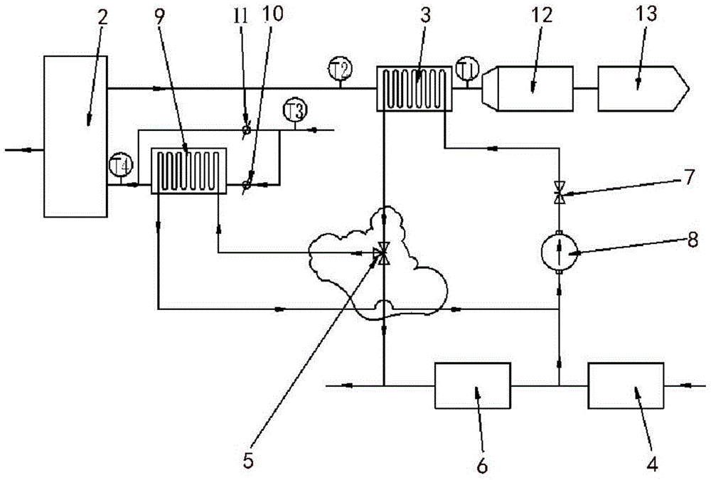
[0020] Such as figure 1 As shown, the boiler flue gas waste heat utilization system of the present invention includes a main pipeline composed of successively connected boiler body, air preheater 2, low temperature heat exchanger 3, and feed water tank 4, the water in the feed water tank 4 is Condensed water, and air preheater air inlet branch, one end of this branch is connected to the air preheater 2, and the air inlet air of the air preheater can be selected to be heated or not, wherein the low temperature heat exchanger 3 and the water supply tank 4 are closed and connected , the outlet pipe of the water supply tank 4 communicates with the inlet and outlet of the low-temperature heat exchanger 3 in turn to form a loop, and also includes a heat recovery distribution system, including a first regulating valve 5, the first regulating valve 5 is a three...


PUM


Abstract

The invention relates to the technical field of power station boiler manufacturing and transformation and discloses a boiler smoke waste heat use system. The system comprises a main pipe formed by the successive connection of a boiler body, an air pre-heater, a cryogenic heat exchanger and a water supply tank and further comprises an air pre-heater air inlet branch and a recovery heat distribution system. The cryogenic heat exchanger and a water supply tank outlet tube form a loop. One end of the branch is connected with the air pre-heater and can be selected to heat or not heat inlet air of the air pre-heater. The recovery heat distribution system is communicated with the cryogenic heat exchanger, the air pre-heater air inlet branch and the water supply tank pipe respectively and can be selected to heat inlet air of the air pre-heater or water in the water supply tank. The recovery heat distribution system can adjust the heated condensation water volume of the main pipe and all branches according to actual needs to control the heat use proportion for heating inlet air or the condensation water of the air pre-heater, and accordingly, the system is adapted to various work conditions, and the boiler heat use rate is improved.

Description

technical field [0001] The invention relates to the technical field of power plant boiler manufacturing and transformation, in particular to a boiler flue gas waste heat utilization system. Background technique [0002] At present, the boiler design is based on the selected air preheater inlet air temperature. In actual operation, the air inlet temperature of the air preheater in summer or high load is higher than the reference temperature, and the exhaust gas temperature is higher; , the air inlet temperature of the air precipitator is lower than the reference temperature, and the exhaust gas temperature is low, which will easily cause corrosion and blockage of the air preheater, affect the boiler efficiency and safe and stable operation, and will also reduce the dust removal efficiency of the electric dust collector and increase the water consumption of the desulfurization process. [0003] In the prior art, in order to solve the problem of low exhaust gas temperature in w...

Claims


Application Information

Patent Timeline
IPC IPC(8): F23L15/00
CPCY02E20/34
Inventor 黄鹏李红兵
Owner DONGFANG BOILER GROUP OF DONGFANG ELECTRIC CORP
Learn More