Evaporative cooling type water chilling unit and control method thereof
A chiller and evaporative cooling technology, which is applied in the direction of refrigerators, refrigeration components, mechanical equipment, etc., can solve the problems of scaling and fouling, and achieve the effect of improving service life and reducing cleaning and maintenance work
- Summary
- Abstract
- Description
- Claims
- Application Information
AI Technical Summary
Problems solved by technology
Method used
Image

Examples
Embodiment 1
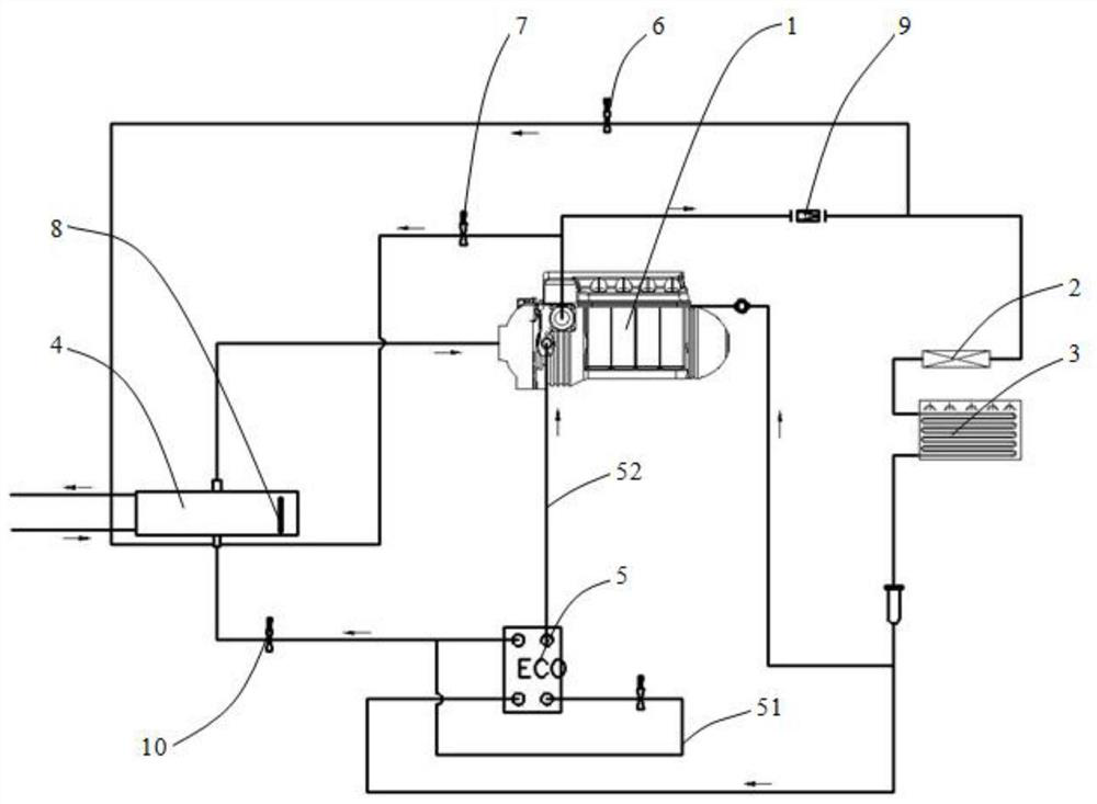
[0043] As shown in the figure, it is a schematic diagram of an evaporative cooling chiller provided in the embodiment of the present invention. The evaporative cooling chiller provided by the present invention includes a compressor 1, a first condenser 2, a second condenser 3, throttling device 10, evaporator 4, compressor 1, first condenser 2, second condenser 3, throttling device 10, and evaporator 4 are connected in sequence to form a refrigeration circuit;
[0044] Compressor 1 The compressor is used to heat and pressurize the low-temperature and low-pressure gaseous refrigerant in the evaporator 4 and transport it to the first condenser 2;
[0045] The first condenser 2 is used to reduce the temperature of the gaseous refrigerant;
[0046] The second condenser 3 is used to condense the refrigerant cooled by the first condenser 2 into a liquid state;
[0047] The throttling device 10 is used to throttle the high-temperature and high-pressure refrigerant liquid after passi...
Embodiment 2
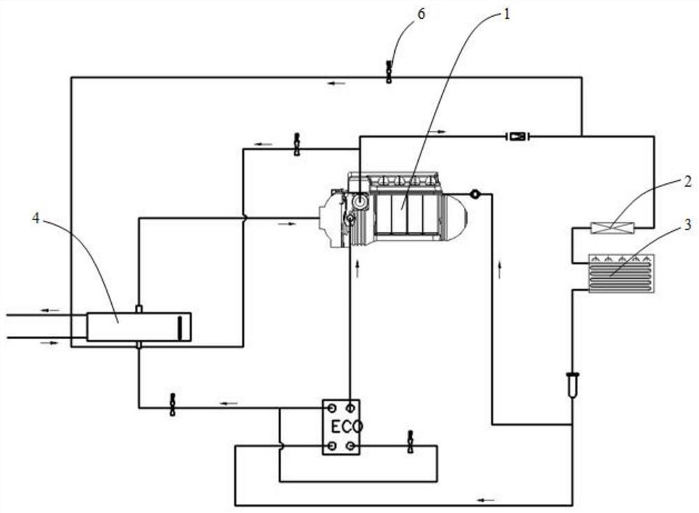
[0069] Another evaporative cooling chiller is provided in the embodiment of the present invention, including a compressor 1, a first condenser 2, a second condenser 3, a throttling device 10, an evaporator 4, a compressor 1, and a first condenser 2. The second condenser 3, the throttling device 10, and the evaporator 4 are sequentially connected to form a refrigeration circuit;
[0070] The compressor 1 is used to heat and pressurize the low-temperature and low-pressure gaseous refrigerant in the evaporator 4 and transport it to the first condenser 2;
[0071] The first condenser 2 is used to reduce the temperature of the gaseous refrigerant;
[0072] The second condenser 3 is used to condense the refrigerant cooled by the first condenser 2 into a liquid state;
[0073] The throttling device 10 is used to throttle the high-temperature and high-pressure refrigerant liquid after passing through the second condenser 3 into a low-temperature and low-pressure refrigerant liquid; ...
Embodiment 3
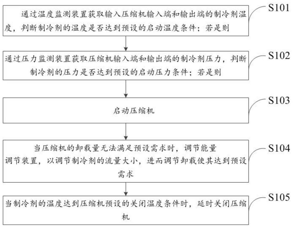
[0080] Such as image 3 As shown, it is a flow chart of an evaporative cooling chiller control method provided in an embodiment of the present invention, and the evaporative cooling chiller used for control includes the following steps:
[0081] Step S101, obtain the temperature of the refrigerant input to the input end and output end of the compressor through the temperature monitoring device, and determine whether the temperature of the refrigerant reaches the preset start-up temperature condition; if so, then
[0082] Step S102, obtain the refrigerant pressure at the input end and the output end of the compressor through the pressure monitoring device, and judge whether the pressure of the refrigerant reaches the preset start-up pressure condition; if so, then
[0083] Step S103, start the compressor;
[0084] Step S104, when the unloading amount of the compressor cannot meet the preset demand, adjust the energy regulating device to adjust the flow rate of the refrigerant,...
PUM
 Abstract
Description
Claims
Application Information
 - Generate Ideas
- Intellectual Property
- Life Sciences
- Materials
- Tech Scout
- Unparalleled Data Quality
- Higher Quality Content
- 60% Fewer Hallucinations
Browse by: Latest US Patents, China's latest patents, Technical Efficacy Thesaurus, Application Domain, Technology Topic, Popular Technical Reports.
© 2025 PatSnap. All rights reserved.Legal|Privacy policy|Modern Slavery Act Transparency Statement|Sitemap|About US| Contact US: help@patsnap.com