
Experimental device and method for simulating gully head drop hole development

A technology of experimental device and experimental method, applied in measurement device, fluid dynamics test, testing of machine/structural components, etc., can solve the problem of difficulty in accurately simulating the development process of burrowing, lack of traceable erosion prediction model of gully head, and the number of gully heads. limited issues

Active Publication Date: 2021-01-29
YUNNAN UNIV
View PDF6 Cites 0 Cited by
  • Summary
  • Abstract
  • Description
  • Claims
  • Application Information

AI Technical Summary

Problems solved by technology

[0004] There are significant differences between falling water erosion and shearing erosion in terms of scouring angle and action mechanism. The design of the flume experimental device for shearing erosion is relatively mature and has been widely used; in contrast, there are few flume experiments for falling water erosion Reported, there is also a lack of a mature drop tank experimental device
[0005] In addition, there is also a test method for observing the runoff-erosion process and the change process of morphological characteristics on the scale of incision ditch head through the simulated erosion test of in-situ ditch head in the field, but the number of ditch heads available for in-situ tests is relatively limited. It is difficult to control other influencing factors such as upstream water and underlying surface conditions, ditch head shape, soil conditions, etc., making it difficult to accurately simulate the development process of the acupoint itself
[0006] Therefore, compared with shear erosion, due to the limitation of experimental means, the simulation research on the source erosion process of the ditch head with falling water as the dynamic condition is still relatively weak. There is still a lack of systematic research on this aspect, resulting in the current lack of practically applicable gully head trace erosion prediction models in the world, which seriously affects the prevention and control of gully erosion

Method used


Image

  • Experimental device and method for simulating gully head drop hole development
  • Experimental device and method for simulating gully head drop hole development

Examples


Embodiment 1

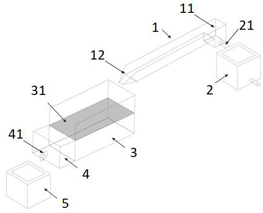
[0054] (1) Adjustment of water drop dynamic conditions: adjust the flow rate of tank 1 to 30 L / min, the slope to 2°, and the height of the water drop to 0.2 meters. Each group of experiments should be washed for 80 minutes, and every 8 minutes is a round of washing;

[0055] (2) Treatment of furrow bed soil: fill the dry red soil into the filling area 31 to form a furrow bed;

[0056] (3) Parameter monitoring:

[0057] Hydraulic parameters: monitor the flow velocity of the runoff in the water tank 1 every 3 minutes, and the 1.5m upward from the outlet 12 is the flow velocity monitoring section. The flow velocity is measured by the dyeing method, and the average value is obtained by repeating 3 times;

[0058] Runoff sediment data: use a 0.25 liter runoff bottle to collect the runoff sediment at 41 sand collection outlets every 1 min, repeat 3 times, and record the total amount of runoff in the grit chamber 5. After fully stirring the grit chamber 5 water sand, Use a runoff bo...

Embodiment 2

[0062] (1) Adjustment of water drop dynamic conditions: adjust the flow rate of tank 1 to 100 L / min, the slope to 15°, and the height of the water drop to 0.6 meters. Each set of experiments is washed for 90 minutes, and every 10 minutes is a round of washing;

[0063] (2) Treatment of furrow bed soil: fill the red soil to the filling area 31 to form a furrow bed;

[0064] (3) Parameter monitoring:

[0065] Hydraulic parameters: monitor the flow velocity of the runoff in the water tank 1 every 5 minutes, and the 2m above the outlet 12 is the flow velocity monitoring section. The flow velocity is measured by the dyeing method, and the average value is obtained by repeating 3 times;

[0066] Runoff sediment data: use a 0.5 liter runoff bottle to collect the runoff sediment at 41 places of the sand collection port every 3 minutes, repeat 3 times, and record the total amount of runoff in the grit chamber 5. After fully stirring the water sand in the grit chamber 5, Use a runoff b...

Embodiment 3

[0070] (1) Adjustment of water drop dynamic conditions: adjust the flow rate of tank 1 to 280 L / min, the slope to 35°, and the height of the drop to 1.0 meters. Each group of experiments is scouring for 100 minutes, and every 10 minutes is a round of scouring;

[0071] (2) Trench bed soil treatment: fill the brick red soil to the filling area 31 to form a ditch bed;

[0072] (3) Parameter monitoring:

[0073] Hydraulic parameters: monitor the flow velocity of the runoff in the water tank 1 every 8 minutes, and the flow velocity monitoring section is 2.5m up from the outlet 12. The flow velocity is measured by the dyeing method, and the average value is obtained by repeating 3 times;

[0074] Runoff sediment data: use 0.5 liter runoff bottle to collect the runoff sediment at 41 places of the sand collection port every 5 minutes, repeat 3 times, and record the total amount of runoff in the grit chamber 5, after fully stirring the water sand in the grit chamber 5, Use a runoff b...


PUM


Abstract

The invention discloses an experimental device and method for simulating gully head drop hole development. The experimental device comprises a first water tank, a second water tank and a desilting basin. The first water tank is located at the upstream of the second water tank, an outlet of the first water tank is located at the position close to the upstream of the center of the second water tank,the upstream of the first water tank is connected with a flow stabilizing pool, and the first water tank is connected with the stabilizing pool through a water pipe. The downstream of the second water tank is connected with a flow collecting tank, and a sand collecting opening is formed in an outlet of the flow collecting tank and aligns to a desilting basin. The following experimental method iscarried out through the experimental device: the water drop power condition of the first water tank is adjusted, the second water tank is filled with different soils, and finally, a photogrammetry technology is utilized to carry out high-precision monitoring on the form of a washed drop hole. According to the invention, the erosion sand production process and morphological characteristics of a ditch bed under the action of drop water under the conditions of different hydrodynamic forces and ditch bed soil conditions are effectively simulated, and the systematic simulation test of the drop holedevelopment process is realized.

Description

technical field [0001] The invention belongs to the technical field of soil and water conservation experiments, and in particular relates to an experimental device and method for simulating the development of ditch heads and pits. Background technique [0002] Gully erosion is the main process of soil erosion, and the contribution of gully erosion to sediment yield in major water erosion areas in my country is as high as 42.9%-86.3%. Erosion at the head of the gully is one of the main processes of the development of gully erosion. The converging stream upstream of the head of the ditch forms falling water at the head of the gully and erodes the bed of the gully, which is the main driving factor for the retreat of the head of the ditch. [0003] The flume test is the main test method to study the soil separation rate under the condition of gust flow erosion. In the early stage, through flume simulation tests in China, the critical development conditions of rills, the separat...

Claims


Application Information

Patent Timeline
Patent Type & Authority Applications(China)
IPC IPC(8): G01M10/00
CPCG01M10/00
Inventor 董一帆段兴武钟荣华荣丽黄江成黄勇
Owner YUNNAN UNIV
Learn More