Driving device, driving system, and driving method for permanent magnet synchronous motor

A technology of permanent magnet synchronous and driving devices, which is applied in the control of electromechanical transmission devices, motor control, motor generator control, etc., can solve the problems of magnetic torque accuracy drop, magnet flux error, etc., and achieve the effect of improving torque accuracy

Pending Publication Date: 2021-01-29
HITACHI LTD
View PDF2 Cites 2 Cited by
  • Summary
  • Abstract
  • Description
  • Claims
  • Application Information

AI Technical Summary

Problems solved by technology

[0009] In the case of driving and controlling the permanent magnet synchronous motor through a drive device in the form of torque control, if the set value K of the constant of the magnet flux set by the controller in the drive device is e * and the actual magnet flux K of the permanent magnet synchronous motor e If there is a difference between them, it will become the error of the magnetic flux of the magnet, which will cause the problem that the accuracy of the magnetic torque will decrease.

Method used


Image

  • Driving device, driving system, and driving method for permanent magnet synchronous motor
  • Driving device, driving system, and driving method for permanent magnet synchronous motor
  • Driving device, driving system, and driving method for permanent magnet synchronous motor

Examples


Embodiment 1

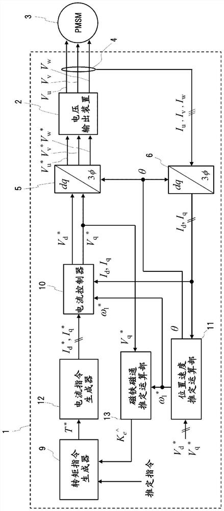
[0047] figure 1 It is a figure which shows the functional block of the drive apparatus of the permanent magnet synchronous motor of Example 1. As a functional block, the structure at the time of estimating the magnetic flux of a magnet is shown in the state which drive-controlled the permanent magnet synchronous motor by the drive apparatus, such as an inverter.

[0048] In addition, in figure 1 In the middle is a functional block diagram for estimating the magnetic flux of the magnet, but the temperature coefficient of the magnet α (% / °C) may be used to convert the magnetic flux and the temperature of the magnet to estimate the temperature of the magnet according to the first embodiment.

[0049] exist figure 1 In the drive device 1 shown, a control program for vector control of the permanent magnet synchronous motor 3 connected as a load is installed. but, figure 1 Only the functional blocks of the minimum structure required for estimating the magnetic flux of the magnet...

Embodiment 2

[0120] Compared with embodiment 1, embodiment 2 is different in the following respects: to the I of current command value d *Assign a predetermined value other than zero, the I q *Estimate the magnet flux or magnet temperature when the value is set to zero and the torque command value is set to zero.

[0121] Figure 7 It is a figure which shows the functional block of the drive apparatus of the permanent magnet synchronous motor of Example 2. The structure at the time of estimating the magnetic flux of a magnet in the state which drive-controlled the permanent magnet synchronous motor by the drive apparatus, such as an inverter, is shown as a functional block.

[0122] In the voltage output device 2, in order to prevent short-circuiting of elements such as IGBTs provided in the upper and lower arms of each phase, a period is set to simultaneously turn off the output elements of the upper and lower arms. When no voltage compensation is applied, this period The output voltag...

Embodiment 3

[0136] Example 3 differs from Example 1 in that the estimated value K of the estimated magnet magnetic flux e ^Store in a storage device such as RAM (Random Access Memory) provided in the control device, and after the storage, based on the stored estimated value K e ^ Carry out drive control, and set the current command value I d *、I q * During the period set to zero, the estimated value K will be stored e ^Updated to the newly estimated value K e ^.

[0137] The thermal time constant of the permanent magnet synchronous motor of the fully enclosed type (the type that does not directly add external air to the airtight equipment) for railways with an output of several hundred kw is about several hours, which is lower than that of a small-capacity motor of several kW The thermal time constant is long. That is, it is not so necessary to always estimate the magnetic flux of the magnet in the drive control, and the temperature fluctuation of the permanent magnet can be grasped ...


PUM


Abstract

When controlling the driving of a permanent magnet synchronous motor, in order to estimate magnet's magnetic flux with high accuracy and robustness against harmonic components of induced voltage and errors in setting constants for resistance and inductance without using a voltage sensor, a speed sensor, and data from magnetic field analysis or experiments, this driving device for a permanent magnet synchronous motor has capability of improving torque accuracy by estimating the amount of magnetic flux or the temperature of the magnet in the permanent magnet synchronous motor on the basis of a voltage command value and speed information about the permanent magnet synchronous motor, in a state in which a current command value when the torque command value is zero is being output, so as to estimate the magnet's magnetic flux or the temperature with high accuracy and robustness against harmonic components of induced voltage and errors in setting constants for resistance and an inductance without using the data from magnetic field analysis or experiments.

Description

technical field [0001] The invention relates to a driving device, a driving system and a driving method of a permanent magnet synchronous motor, and is especially suitable for railway vehicles. Background technique [0002] In electric motor drive devices for railway vehicles, vector control capable of achieving high response and high precision of torque control is widely used. In recent years, the application of permanent magnet synchronous motors has been promoted for the purpose of downsizing and improving the efficiency of drive systems for railway vehicles. [0003] In the vector control of the permanent magnet synchronous motor, the direction of the magnetic flux of the magnetic pole generated by the permanent magnet of the rotor of the permanent magnet synchronous motor is defined as the d-axis, and the direction perpendicular to the d-axis is defined as the q-axis. Voltage, current, and flux are handled in a vertical coordinate system in which the flux rotates synch...

Claims


Application Information

Patent Timeline
Patent Type & Authority Applications(China)
IPC IPC(8): H02P21/14H02P21/22H02P29/62
CPCH02P21/14H02P21/141H02P29/662
Inventor 国广直希筱宫健志大塚邦晃坂井俊文石川胜美
Owner HITACHI LTD
Why Eureka
Try Eureka