
Rear-mounted ditcher soil dividing wing

A trencher, rear-mounted technology, which is applied in the field of soil separation wings, can solve the problems of soil accumulation in hard corners, soil blocks can not be spread evenly from near to far, and difficult to manufacture soil separation wings, etc., and achieves wear-resistant adhesion. Soil, reducing adhesion to soil or even clogging the trencher, the effect of not easily adhering to soil

Inactive Publication Date: 2021-02-02
葛伟岸 +1
View PDF0 Cites 0 Cited by
  • Summary
  • Abstract
  • Description
  • Claims
  • Application Information

AI Technical Summary

Problems solved by technology

The disadvantage is that the weld on the lower edge is easy to crack and damage, because the material thickness of the soil wing is relatively thin, generally only between 1.5 and 3.0 mm, it is difficult to weld firmly, and the lower edge has to bear the continuous and intense impact of the soil block, Therefore, it is easy to be damaged, the labor intensity of welding is high, the surface of the weld seam is rough, and the production efficiency is low, which is a problem that has plagued manufacturers and users for many years.
The technology published on November 20, 2018 with the publication number CN 10883441 A adopts a sub-soil wing structure in which the upper and lower lower edges are spliced ​​in a straight line. The lower half of this technology is folded into a V shape with a plate, trying to Solve the problems of difficulty in manufacturing and unstable quality of the above-mentioned soil splitting wings, but because the joint is not a smooth arc, it cannot match the arc parabola of the soil block projection, and there is siltation of soil at the hard corners, and the uniformity of soil throwing is not very good ideal
[0003] The front and rear V-shaped angles of the soil dividing wings in the prior art do not change, so that the throwing angles, heights and distances of all soil clods are similar, and the soil clods cannot be spread evenly from near to far
[0004] The root of the soil splitter wing is connected to the crossbeam with four bolts, and the distance between the soil splitter wing and the tip of the cutter head cannot be adjusted to meet the needs of different soil properties.

Method used


Image

  • Rear-mounted ditcher soil dividing wing
  • Rear-mounted ditcher soil dividing wing
  • Rear-mounted ditcher soil dividing wing

Examples


Embodiment Construction

[0019] The present invention is described in further detail in conjunction with embodiment now.

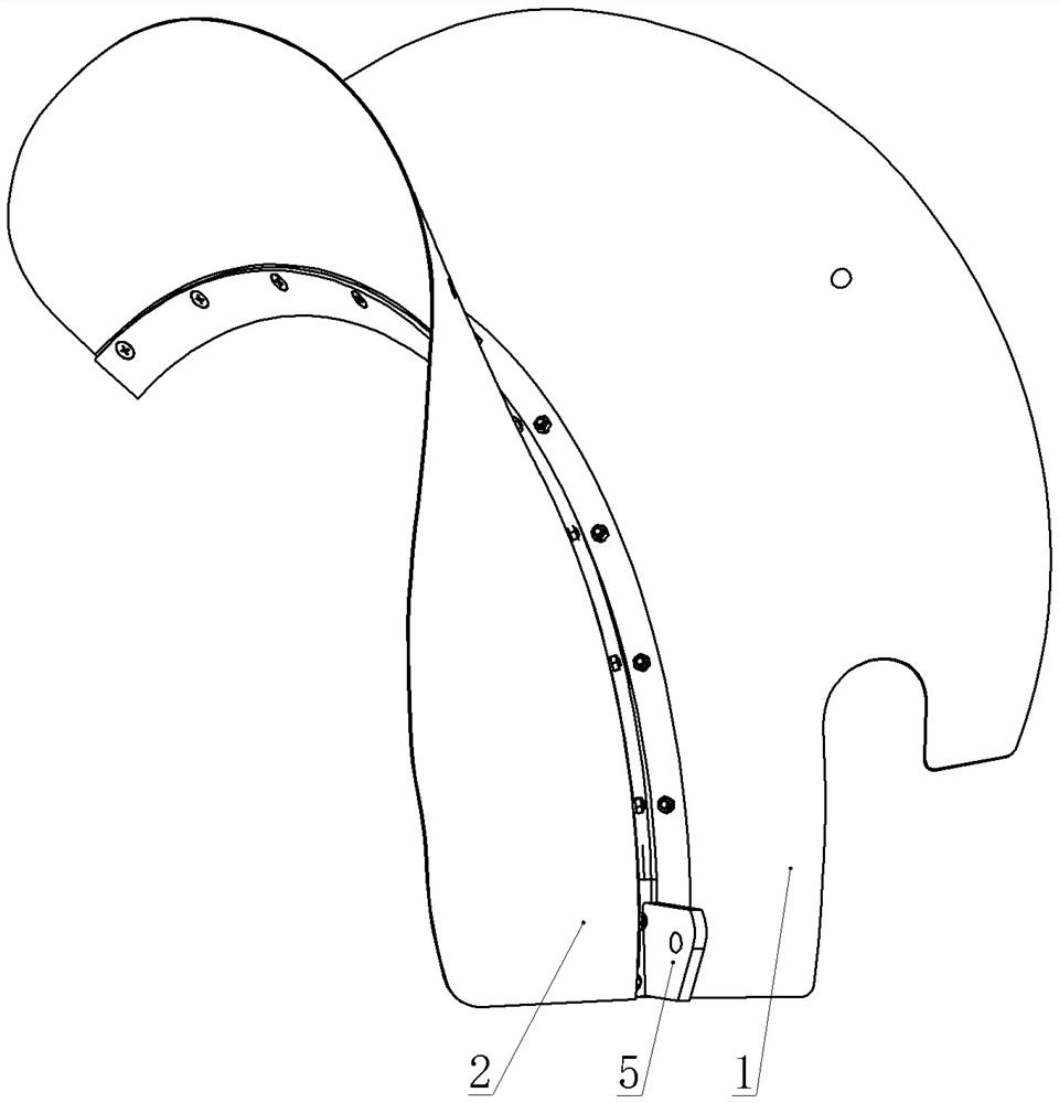
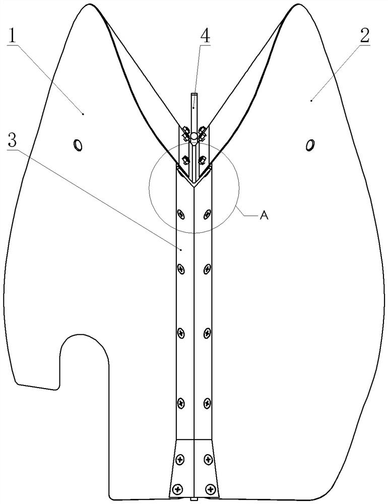
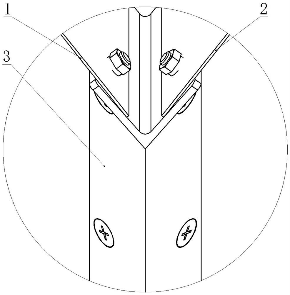
[0020] Such as Figure 1 to Figure 5 As shown, the present invention discloses a rear-mounted ditching machine soil-distributing wing. The soil-dividing wing is composed of two left-wing plates 1 and right-wing plates 2 whose upper and lower edges are arc-shaped, and one bent into a cross-section of V It is composed of arc-shaped bow beam 3 viewed from the axial direction of the cutter head. There are several through holes evenly arranged at the junction of the lower edge of the left wing plate 1 and the right wing plate 2 and the bow beam 3, which are assembled with bolts or riveted with rivets. Above the inner side of the V-shaped bow beam 3 . The used bolt is a countersunk head, and the lower part of the V-shaped outer side of the bow beam 3 is processed with a countersunk hole corresponding to the bolt, which can also be riveted with a countersunk rivet.

[0021] Such as F...


PUM


Abstract

The invention provides a rear-mounted ditcher soil dividing wing which comprises a left wing plate and a right wing plate, wherein the left wing plate and the right wing plate are placed on the innerside of the upper portion of a bow beam, the arch arc of the bow beam is close to the arcs of the lower edges of the left wing plate and the right wing plate, a plurality of mutually corresponding through holes are evenly formed in the joint of the left wing plate and the right wing plate, and the left wing plate and the right wing plate are assembled through screws or riveted to the upper portionof the bow beam through rivets. The bow beam is formed by bending a whole piece of a thicker material into a V shape and can tolerate impact abrasion of soil blocks, the defect that a welding seam atthe lower edge of the soil dividing wing is prone to cracking due to unstable welding quality is overcome, the assembly is faster than a welding process, and conditions for using stainless steel or ahigh-carbon steel sheet and other materials which are not easily welded are created; the stainless steel or high-carbon steel sheet is wear-resistant and cannot adhere to soil easily; front and rearincluded angles of the soil dividing wing are different, so that the soil throwing heights and distances are inevitably different, and the effect of uniformly distributing the soil blocks on two sidesof a ditch is achieved; and the distance between the lower arch arc of the soil dividing wing and the tool nose is convenient to adjust, the soil throwing height and the width towards the two sides can be integrally adjusted, and the requirements of different field plots and soil properties are met.

Description

technical field [0001] The invention belongs to the field of agricultural machinery and relates to a soil dividing wing of a rear-mounted ditching machine. Background technique [0002] The top of the existing ditching machine is all provided with curved soil-distributing wings, and its effect is to scatter the soil clods that are cut out by the cutter head and projected upward at high speed to both sides of the ditch. Seen from the axial direction of the cutter head, that is, the right side of the ditching machine, the shape of the soil splitting wing is an upwardly arched half-moon shape, and the curved edge of the lower side is slightly larger than the maximum rotation radius of the blade on the cutter head. Since the lower edge is a curved arc Generally, the lower edges of two curved arc plates can only be connected by welding. The disadvantage is that the weld on the lower edge is easy to crack and damage, because the material thickness of the soil wing is relatively t...

Claims


Application Information

Patent Timeline
IPC IPC(8): A01C5/06
CPCA01C5/064
Inventor 葛玉明葛伟岸葛桂萍周雪梅
Owner 葛伟岸
Learn More