
Full-automatic assembly line system for electrostatic powder coating

An electrostatic powder and assembly line technology, applied in the direction of electrostatic spraying device, spraying device, liquid spraying equipment, etc., can solve the problems of poor coating effect, single function, increased workload, etc., achieve flexible position changes, expand the spraying area, reduce The effect of powder waste

Active Publication Date: 2021-02-02
明德新材料科技(浙江)股份有限公司
View PDF5 Cites 4 Cited by
  • Summary
  • Abstract
  • Description
  • Claims
  • Application Information

AI Technical Summary

Problems solved by technology

[0002] Electrostatic powder spraying is commonly known as "electrostatic spraying"; electrostatic powder spraying uses a coating machine with an atomizing nozzle (to atomize the paint) and a discharge level (to generate electricity and current) to atomize the paint, apply a charge to it, and connect the electrode and the paint. An electric field is formed between the objects to be coated, and the electrostatic adsorption is used for coating; the existing electrostatic coating equipment on the market generally uses a single row of array spray guns to spray on both sides at the same time, so that the coating of the workpiece can be completed at one time; this spraying method It is often necessary to spray twice or even three times the amount of powder that exceeds the amount of coating at one time to ensure that there is no blank area for coating, so that a large amount of powder will accumulate at the bottom of the coating chamber, which needs to be recycled, screened and repainted regularly. Utilization increases the workload; at the same time, this coating method is more friendly to plate workpieces, and the coating effect on polyhedrons and irregular shapes is poor, and the function is relatively single

Method used


Image

  • Full-automatic assembly line system for electrostatic powder coating
  • Full-automatic assembly line system for electrostatic powder coating
  • Full-automatic assembly line system for electrostatic powder coating

Examples


Embodiment Construction

[0024] In order to enable those in the technical field to better understand the solutions of the present invention, the technical solutions in the embodiments of the present invention will be clearly and completely described below in conjunction with the drawings in the embodiments of the present invention.

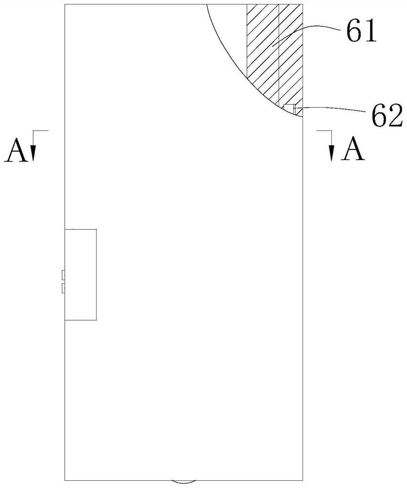
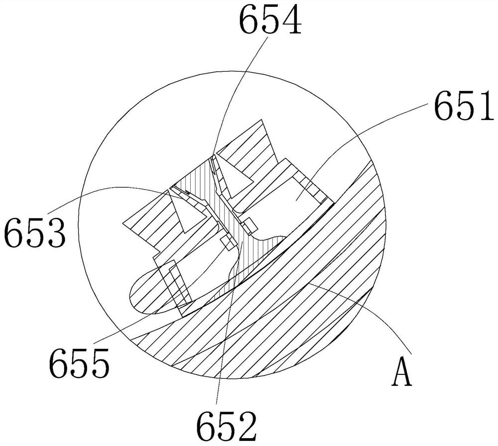
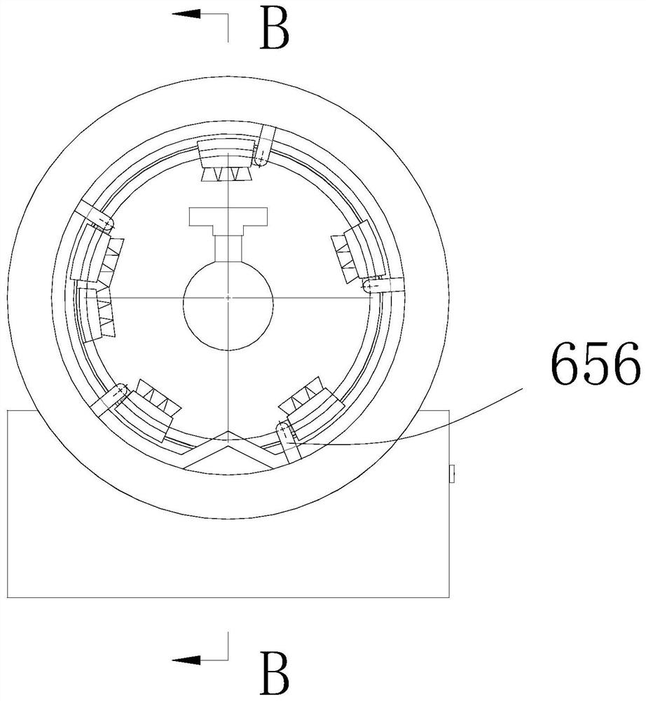
[0025] Such as Figure 1-15As shown, a fully automatic assembly line system for electrostatic powder coating, including a fixed base 1, a non-contact powder bin 2, a powder recovery system 3, a cylindrical coating bin 4, a suspension conveying structure, a first-stage powder spraying structure 6, two Level powder spraying structure 7 and leveling mechanism 8; the non-contact powder bin 2 is set inside the fixed base 1; the powder recovery system 3 is set in the non-contact powder bin 2; the cylindrical coating The bin 4 is fixedly connected to the fixed base 1; the suspension conveying mechanism 5 is arranged inside the cylindrical coating bin 4; the primary powder sprayi...


PUM


Abstract

The invention discloses a full-automatic assembly line system for electrostatic powder coating. The full-automatic assembly line system comprises a fixed base, a non-contact powder bin arranged on thebase, a powder recycling system arranged on the non-contact powder bin, a barrel type coating bin fixedly connected to the fixed base, a suspension conveying mechanism arranged on the barrel type coating bin, a primary powder spraying structure arranged on the barrel type coating bin, a secondary powder spraying structure arranged on the rear side of the primary powder spraying structure and a leveling mechanism arranged on the secondary powder spraying structure. The two spraying structures are arranged, the spraying area between of a flowing water chamber is enlarged, the conveying speed ofthe suspension conveying structure can be further increased, and therefore the working efficiency is improved. And the powder recycling system is arranged and matched with the barrel type coating binso that powder can be recovered and utilized in time, powder waste is reduced, and the cost is also reduced.

Description

technical field [0001] The invention belongs to the technical field of electrostatic powder coating, and in particular relates to an automatic assembly line system for electrostatic powder coating. Background technique [0002] Electrostatic powder spraying is commonly known as "electrostatic spraying"; electrostatic powder spraying uses a coating machine with an atomizing nozzle (to atomize the paint) and a discharge level (to generate electricity and current) to atomize the paint, apply a charge to it, and connect the electrode and the paint. An electric field is formed between the objects to be coated, and the electrostatic adsorption is used for coating; the existing electrostatic coating equipment on the market generally uses a single row of array spray guns to spray on both sides at the same time, so that the coating of the workpiece can be completed at one time; this spraying method It is often necessary to spray twice or even three times the amount of powder that exc...

Claims


Application Information

Patent Timeline
Patent Type & Authority Applications(China)
IPC IPC(8): B05B5/08B05B13/02B05B14/48
CPCB05B5/081B05B5/082B05B14/48B05B13/0264B05B13/0278Y02P70/10
Inventor 李俊郭颖
Owner 明德新材料科技(浙江)股份有限公司
Learn More