
Special boring clamp

A technology for boring fixtures and bushing holes, which is used in clamping, manufacturing tools, drilling dies for workpieces, etc., can solve the problems of dislocation of processing and clamping and high processing scrap rate, achieve accurate and rapid positioning, and reduce scrap rate. , The effect of improving the clamping efficiency

Inactive Publication Date: 2021-02-02
蒋元明
View PDF0 Cites 2 Cited by
  • Summary
  • Abstract
  • Description
  • Claims
  • Application Information

AI Technical Summary

Problems solved by technology

[0004] The purpose of the present invention is to provide a special boring jig, and at the same time provide the core manufacturing process and control requirements of the jig, so as to solve the problem of misalignment of processing and clamping of specific outer arc-shaped cavity parts and inner rack components, and the extremely high processing scrap rate The problem

Method used


Image

  • Special boring clamp
  • Special boring clamp
  • Special boring clamp

Examples


Embodiment 1

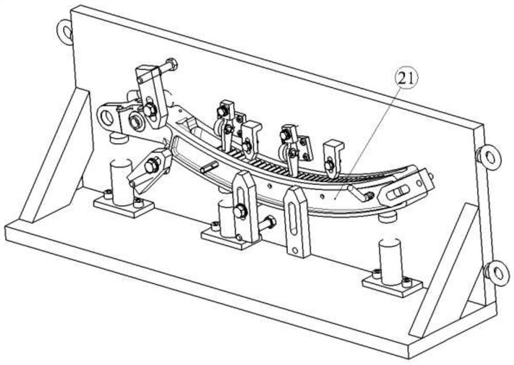
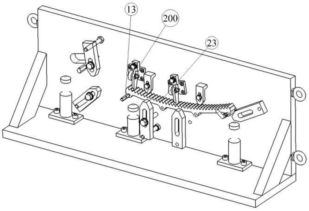
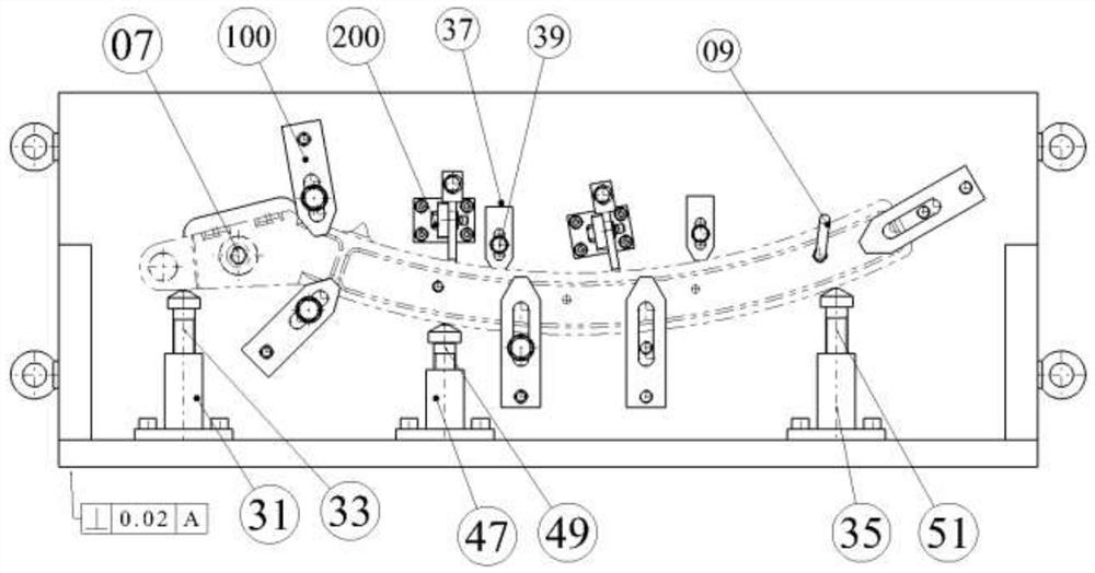
[0023] see Figure 1~9 , a special boring jig, consisting of a main positioning plate 01, a base plate 03, a reinforcing plate 05, a positioning origin bushing 11, a diamond-shaped positioning pin 07, a drilling mold assembly, a first platen assembly 100, a second platen assembly, the first The jacking support assembly, the second jacking support assembly, the third jacking support assembly, and the internal rack pressing assembly 200 are composed. The main positioning plate is provided with an avoidance groove 46, the two sides of the main positioning plate are provided with eyebolt bottom holes, and four eyebolts 29 are fixedly installed on both sides of the main positioning plate, which is convenient for hoisting. The hole jig is heavy in weight. The two planes of the main positioning plate are ground and processed to ensure the parallelism within 0.02. The main positioning plate is vertically installed on the bottom plate through the screw pin structure, and the two ends ...


PUM


Abstract

The invention relates to a special boring clamp which is composed of a main positioning plate, a bottom plate, a reinforcing plate, a positioning origin bushing, a rhombic positioning pin, drill jig assemblies, a first pressing plate assembly, a second pressing plate assembly, a first jacking supporting assembly, a second jacking supporting assembly, a third jacking supporting assembly and an inner rack pressing assembly. An origin bushing hole, a rhombus pin hole and three drill jig sleeve holes are machined in the main positioning plate, the special boring clamp is provided with three same drill jig plate assemblies according to the characteristics of machined products, and each drill jig assembly is composed of a first drill sleeve, a second hinge sleeve, a third hinge sleeve and a fastening locking screw. The first pressing plate assembly is composed of a flat pressing plate, a first pressing plate locking bolt, a first spring pad, a first supporting bolt and a first locking nut, and the inner rack pressing assembly is composed of a T-shaped support, a hook-shaped top pressing plate, a rotating shaft pin, a cotter pin, a third locking bolt, a spherical elastic pad and a conicalelastic pad. By means of the scheme design of the special boring clamp, the machining problems that when a specific outer arc-shaped cavity piece and an inner rack assembly are machined, positioningand clamping are difficult, dislocation is likely to happen, and scrapping is likely to happen are solved.

Description

technical field [0001] The invention relates to a boring jig, in particular to a special boring jig for a horizontal boring machine. Background technique [0002] The horizontal boring machine still has certain processing advantages for horizontal clamping or when the lateral depth of the boring hole is required to be deep. However, for some complex parts, especially those with high difficulty in clamping, complex shapes and high processing requirements, special boring fixtures must be designed to assist in the use of horizontal boring machines to meet processing requirements. There is a class of components with a relatively complex shape and an arc shape. The inner rack needs to be nested in the outer arc cavity and bored together. The material of the inner rack is hard, and the material of the outer arc cavity is relatively low in hardness. At the same time, when the two nested boring holes, there are high requirements on the hole diameter and hole position, which leads t...

Claims


Application Information

Patent Timeline
IPC IPC(8): B23B47/28B23Q3/06
CPCB23B47/28B23B2247/12B23Q3/062
Inventor 蒋元明
Owner 蒋元明
Learn More