Supercharge Your Innovation With Domain-Expert AI Agents!

Copper strip foil degreasing cleaning line

A degreasing cleaning and copper strip technology, applied in the field of copper strip processing, can solve the problems of increased cost and environmental protection pressure, large loss of degreasing agent, small tension adjustment margin, etc.

Active Publication Date: 2021-02-02
ANHUI ZHONGYUAN NEW MATERIALS CO LTD
View PDF7 Cites 0 Cited by
  • Summary
  • Abstract
  • Description
  • Claims
  • Application Information

AI Technical Summary

Problems solved by technology

[0003]The existing degreasing and cleaning line can stably clean common thickness copper strips, but it is difficult to stably clean ultra-thin copper strips with a thickness of about 0.007mm, and there are the following problems: 1. After cleaning, rubber rollers are often used to squeeze dry. However, for ultra-thin copper strips with a thickness of about 0.007mm, it is difficult to achieve a better squeezing effect with traditional rubber rollers; Squeeze the pressure of the rubber roller, and the ultra-thin copper strip is easy to deform; if the pressure is small, the squeezing effect will be poor and affect the product quality; therefore, it is difficult to achieve a good squeezing effect with the existing rubber roller; 2. The existing cleaning The tension of the wire copper strip is mostly adjusted by the S roller; but because the S roller tension adjustment structure is inherently rigid in transmission, the S roller tension adjustment margin is small, and the tension adjustment of the ultra-thin copper foil strip with a thickness of only about 0.007mm is not enough. Too suitable, when the tension is adjusted, the ultra-thin copper strip tension adjustment is prone to broken strips, which affects production efficiency; 3. The degreasing liquid after cleaning is mixed with rolling oil, especially the degreasing liquid in the first-level degreasing cleaning box, resulting in cleaning and degreasing The loss of the agent is large, and because the degreasing liquid containing dirty oil cannot be reused, the cost and environmental protection pressure are increased

Method used


Image

  • Copper strip foil degreasing cleaning line
  • Copper strip foil degreasing cleaning line
  • Copper strip foil degreasing cleaning line

Examples


specific example

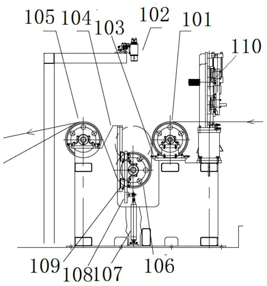
[0064] The non-woven fabric vacuum squeeze roller assembly 201 includes a hollow roller core, a perforated spacer and a non-woven fabric located outside the roller core, an intermediate retaining ring 203 compresses and fixes the non-woven cotton core 207, and the inner retaining ring 205 The holed spacer 206 is fixed, and finally the outer fastening nut 204 is qualitatively fastened. In consideration of preventing back loosening, the position is fixed by the outer locking nut positioning pin 209 .

[0065] The vacuum suction passes through the mandrel hole 208, and is drawn out from the vacuum suction hole 210 through the vacuum suction through hole 211. The vacuum suction power comes from a very mature Roots blower.

[0066] After the suction device with the Roots blower as the vacuum source is started, a negative pressure is formed in the shaft core. When the strip passes through the roll surface, due to the capillary characteristics of the non-woven fabric on the roll surfa...


PUM


Abstract

The invention discloses a copper strip foil degreasing cleaning line. A floating roller capable of moving up and down to achieve adjustment is adopted in front of a degreasing cleaning box in the cleaning line to ensure the tension of a copper strip, the tension adjusting allowance is large, the tension of an ultrathin copper foil strip of 0.007 mm can be stably adjusted, the problem of strip breakage is not prone to occurring, and therefore it is guaranteed that the copper foil strip is stably wound; after cleaning, a non-woven fabric squeezing roller structure of negative pressure suction isadopted so that a liquid extrusion area can be formed on the feeding side and a rebound negative pressure adsorption area can be formed on the discharging side, and compared with a traditional rubbersqueezing roller, a better squeezing effect is achieved; and a good squeezing effect can be achieved by adopting small pressure, the cleaning line is especially suitable for ultrathin copper strips with the thickness being about 0.007 mm, copper strips are not prone to being damaged, and the quality of finished products is greatly guaranteed.

Description

technical field [0001] The invention relates to the technical field of copper strip processing, in particular to an ultra-thin copper strip foil degreasing and cleaning line. Background technique [0002] In the production process of copper strip and foil, the surface degreasing treatment of copper strip and foil is an important process to improve the quality of the product. The basic process of this process is: uncoiling → degreasing cleaning → squeezing → drying oven → winding. The treatment agent and water remaining on the surface of the copper calendered high-conductivity copper foil need to be squeezed and dried. [0003] The existing degreasing and cleaning line can stably clean copper strips of ordinary thickness, but it is difficult to clean them stably for ultra-thin copper strips with a thickness of about 0.007mm. For ultra-thin copper strips with a thickness of about 0.007mm, it is difficult to achieve a better drying effect through traditional rubber rollers; if...

Claims


Application Information

Patent Timeline
IPC IPC(8): C23G3/02
CPCC23G3/02C23G3/026C23G3/029C23G3/027
Inventor 谢维维吴小兵
Owner ANHUI ZHONGYUAN NEW MATERIALS CO LTD
Features
  • R&D
  • Intellectual Property
  • Life Sciences
  • Materials
  • Tech Scout
  • Unparalleled Data Quality
  • Higher Quality Content
  • 60% Fewer Hallucinations
Learn More