Downhole pressurizing water injection device and method

A booster device and water injection pipe technology, which is applied to parts of pumping devices for elastic fluids, earthwork drilling, wellbore/well parts, etc., and can solve low economic benefits, inconvenient transportation, and pressure loss of injected water delivery major issues

Pending Publication Date: 2021-02-02
PETROCHINA CO LTD
View PDF4 Cites 2 Cited by
  • Summary
  • Abstract
  • Description
  • Claims
  • Application Information

AI Technical Summary

Problems solved by technology

[0004] In oilfield exploration and development, remote well areas are far away from power grids, production pipelines and water injection stations, and the original water injection stations are used to pressurize and inject water into injection wells. The long-distance transmission of injected water has a large pressure loss, and the pressure of injected water reaching the formation of water injection wells cannot reach To meet the requirements, and maintain high-pressure transmission of injected water on the ground, there are many potential safety hazards; remote well areas have harsh environments, sparsely populated, and inconvenient transportation. Separately build stations and lay pipelines in remote well areas, construction and maintenance of ground booster devices and corresponding water grid costs High, low economic benefit

Method used


Image

  • Downhole pressurizing water injection device and method
  • Downhole pressurizing water injection device and method

Examples


Embodiment Construction

[0038] In order to make the object, technical solution and advantages of the present invention clearer, the present invention will be further described in detail below in conjunction with the accompanying drawings.

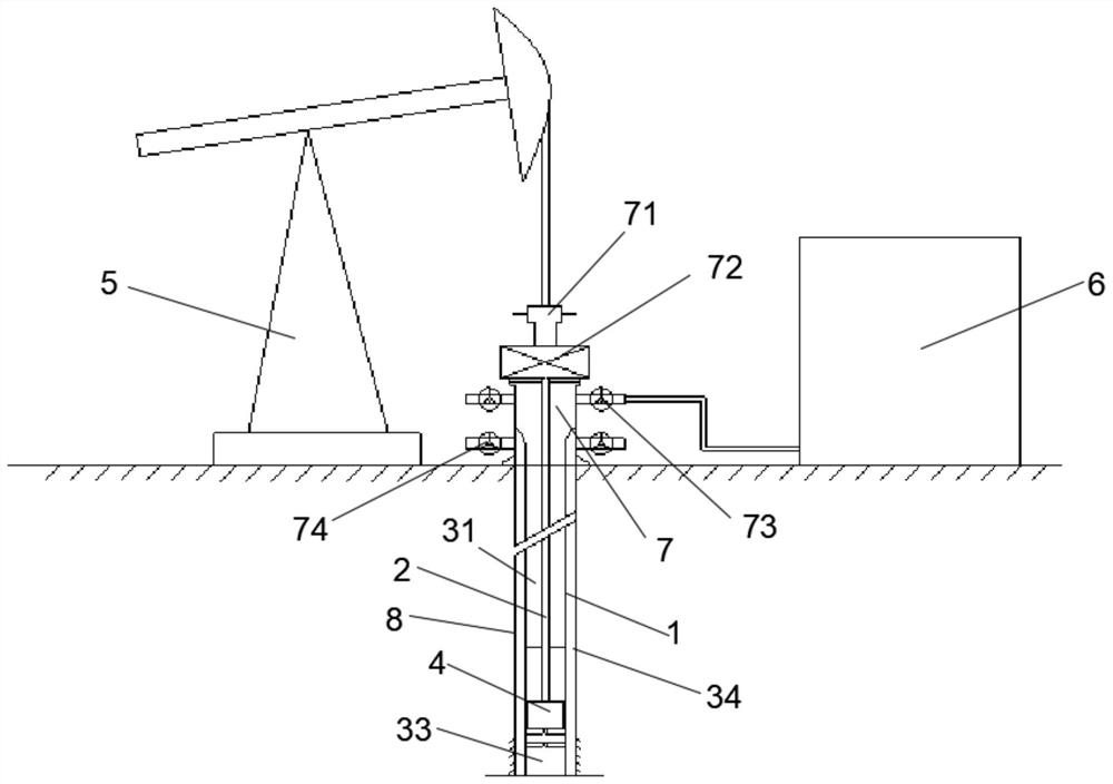
[0039] Such as figure 1 , figure 2 As shown, the downhole pressurized water injection device disclosed by the present invention includes a water injection pipe 1, a water injection rod column 2, a driving device 5, a piston type pressurized device 4, a wellhead joint 7 and a water supply device 6. The well and the lower end are connected to the oil layer. The piston type booster device 4 is arranged in the water injection pipe 1. The piston type booster device 4 is fixedly connected with the inner wall of the water injection pipe 1 and the joint is sealed. The bottom end of the water injection rod column 2 is connected to the piston type booster The piston 422 of the device 4 is fixedly connected, the wellhead joint 7 is arranged at the wellhead of the well, the...


PUM


Abstract

The invention discloses a downhole pressurizing water injection device. The downhole pressurizing water injection device comprises a water injection pipe, a water injection rod column, a driving device, a piston type pressurizing device, a wellhead connector and a water supply device, wherein the water injection pipe is arranged inside a well, the lower end of the water injection pipe communicateswith an oil layer, the piston type pressurizing device is fixedly connected to the inner wall of the water injection pipe and the connecting portion is sealed, the bottom end of the water injection rod column is fixedly connected with a piston of the piston type pressurizing device, the wellhead connector is arranged at a wellhead, the top end of the water injection pipe is connected with the wellhead connector in a sealed mode, the top end of the water injection rod column upwards penetrates out of the wellhead connector and then is connected with the driving device, the driving device and the water supply device are both arranged on the ground of the wellhead, and the water supply device communicates with the water injection pipe. The invention further provides a downhole pressurizing water injection method adopting the above downhole pressurizing water injection device. According to the downhole pressurizing water injection device and method, a ground pressurizing device is not needed, more safety is achieved, and technical support is provided for water injection failure and remote well single well tank water injection caused by the fact that a mechanical production well is converted into a water injection well and the wellhead pressure of the water injection well is high.

Description

technical field [0001] The invention relates to the field of petroleum exploitation, in particular to an underground pressurized water injection device and method. Background technique [0002] In the process of oil production, the self-spraying time of the oil well only accounts for a small part of the entire production process. As the oil well enters the late stage of production, the formation pressure continues to drop. When the formation pressure is not enough to drive crude oil into the wellbore, water injection is required. Method to drive oil. [0003] Oil field water injection is one of the important means to replenish energy to the formation and improve oil recovery in the process of oil field development. At present, oil field water injection mainly adopts the surface water injection method. The surface water injection method of the oil field is to increase the pressure of the injected water through a high-pressure water injection pump. After the injected water re...

Claims


Application Information

Patent Timeline
Patent Type & Authority Applications(China)
IPC IPC(8): E21B43/20F04B17/00F04B53/10F04B53/12
CPCE21B43/20F04B17/00F04B53/1002F04B53/126
Inventor 刘战君彭翔张正平郑雷陈学辉苗国政孙梦慈景士宏李安军张启龙兰芳邓小茹寇明富王其年王美强孙炜高亮党晓丽孙春梅王丽霞傅建军岳刚张长津李科唐良文刘向南严小龙张鑫
Owner PETROCHINA CO LTD
Why Eureka
Try Eureka