Embedded tuning circuit board probe for testing radio frequency signals based on radio frequency-free test socket

A radio frequency test socket and radio frequency signal technology, applied in the direction of measuring electricity, measuring electrical variables, and electronic circuit testing, etc., can solve problems such as weakening the effect of impedance matching, and achieve the effect of ensuring effectiveness, convenient application, and reducing operational complexity.

Active Publication Date: 2021-02-02
深圳合一测试科技有限公司
View PDF11 Cites 5 Cited by
  • Summary
  • Abstract
  • Description
  • Claims
  • Application Information

AI Technical Summary

Problems solved by technology

[0004] On the basis of saving the design of the radio frequency test seat, the inventor found that the test can be carried out by direct mechanical contact with the antenna shrapnel, during which a certain impedance matching adjustment is required to meet the preconditions of the test, so as to have a good test effect, because The traditional board-level test path of the mainboard of wireless products is constructed by using RF test sockets, RF probes and RF cables with an impedance of 50 ohms. The impedance of the entire path is continuous. When the shrapnel is in mechanical contact with the radio frequency test of the main board of the wireless product, the test path impedance of the antenna matching circuit component between the RF chip and the antenna shrapnel is not continuous at 50 ohms. It will correspond to the unused antenna matching circuit, so after the RF test probe, it is necessary to set impedance matching for tuning to make the entire board-level path testable. However, it is found in the research that the setting position of the module with tuning function in the circuit is also It will affect the effect of impedance matching. If the tuning module is added after the RF test probe, the effect of impedance matching will be weakened due to the 50 ohm impedance transmission line of the RF test probe itself; so in the above technical background Next, it is also necessary to solve the problem of how to set the relative position relationship between the RF test probe and the tuning module circuit board, so as to ensure that the impedance matching effect will not be affected under the test without the RF test socket

Method used


Image

  • Embedded tuning circuit board probe for testing radio frequency signals based on radio frequency-free test socket
  • Embedded tuning circuit board probe for testing radio frequency signals based on radio frequency-free test socket
  • Embedded tuning circuit board probe for testing radio frequency signals based on radio frequency-free test socket

Examples


Embodiment 1

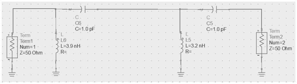
[0072] see Figure 12 , the figure shows the specific circuit form of the antenna matching circuit and tuning components of a certain brand of wireless product motherboard, PORT1 represents the RF chip end, PORT2 represents the test instrument end, and the antenna shrapnel (ANT CLIP CONTACT) to PORT1 is the antenna matching The circuit is composed of capacitor C2 and inductor L3. The circuit between the antenna shrapnel and PORT2 is a tuning component, from Figure 9 It can be seen that the circuit of the tuning component and the antenna matching circuit are matched together to form a dual-port symmetrical structure network, and the purpose is to ensure the symmetry of the RF S parameters of port 2 (PORT2) and port 1 (PORT1). Since the antenna supports the two frequency bands N78 and N79 at the same time, according to the composition of the wireless product antenna matching circuit (capacitor C2 and inductor L3), after debugging, it is found that it is necessary to use single-...

Embodiment 2

[0089] see Figure 17 , Figure 23-25 , Figure 17 There are three circuit parts, ABC, respectively, and the C part circuit is the antenna matching circuit of the wireless product motherboard (4G antenna). The matching form used in the frequency band, that is, when the circuit of part C is changed, the circuits of parts A and B are adjusted to achieve the overall symmetrical form of ABC. After debugging, it is found that the single-pole double-throw RF switches U4 and U5 in the B frame need to be used to switch the π-type tuning circuit series adjustable capacitor C224, and the single-pole four-throw RF switches U6 and U7 in the B frame need to be used. In order to ensure symmetry, the values ​​of the components switched to the ground must be the same for the switching of the component values ​​on the two branches connected in parallel to the ground of the tuning circuit.

[0090] When the RF chip works in the B5 frequency band (824-894MHz), the single-pole double-throw switc...

Embodiment 3

[0101] see Figure 20-22 , since the symmetrical form of the circuit can be composed of a variety of components selected and arranged in specific settings, it should not be understood that the implementation of the present invention is limited to the examples in the description, such as the commonly used T-type and π-type symmetrical network forms. According to the number of components, it can also be divided into one-stage parallel π-type, three-stage π-type and three-stage T-type, and the tuning components mentioned in the present invention include but are not limited to the above-mentioned forms.

[0102] The advantages of the present invention are:

[0103] 1) By using the present invention, the radio frequency test socket can be directly omitted, and the tuning component with impedance matching function is embedded in the package shell, welded on the tuning component through the signal pin, and directly contacts the antenna shrapnel through the signal pin to form a path; ...


PUM


Abstract

The invention relates to an embedded tuning circuit board probe for testing a radio frequency signal based on a radio frequency-free test socket. The embedded tuning circuit board probe is applied toa test system of the radio frequency-free test socket. The probe comprises a tuning assembly, the tuning assembly is electrically connected with a signal pin, the signal pin is connected with an antenna matching circuit of a mainboard to be tested, the tuning assembly is further provided with a connection port, and the connection port is used for connecting a radio frequency test cable and a control line of the tuning assembly and is connected with an external test instrument through the radio frequency test cable, a control line of the tuning assembly is used for receiving a control signal, so that impedance matching is performed between the tuning assembly and the antenna matching circuit, the purpose of omitting a radio frequency test seat is achieved; the tuning assembly is embedded inthe radio frequency test needle, and the signal needle and the connection port are connected to the tuning assembly, so that the resistance and interference caused by the radio frequency test probe and the radio frequency line are reduced, the operation complexity of impedance matching of the whole path is reduced, the adjustment time and the verification time are saved, and the effectiveness ofthe detection effect is ensured, the structural size is reduced, and the application is convenient.

Description

technical field [0001] The invention relates to the technical field of radio frequency signal testing, in particular to an embedded tuning circuit board probe for testing radio frequency signals based on a non-radio frequency test socket. Background technique [0002] In recent years, with the continuous development of communication technology, the popularity of wireless products has become higher and higher, and the number of wireless products produced in the world is also increasing every year, and people's production and life are becoming more and more convenient. Wireless products (represented by mobile phones) mainly refer to the communication frequency of 300kHz ~ 300GHz, and the communication signals in this frequency range are also called radio frequency signals. In order to ensure the quality of the RF signal on the motherboard of wireless products and meet a series of the most basic wireless communication requirements of wireless products, it is usually necessary t...

Claims


Application Information

Patent Timeline
IPC IPC(8): G01R1/067G01R1/073G01R31/28G01R1/04
CPCG01R1/0416G01R1/06733G01R1/06772G01R1/073G01R31/2884G01R31/2889
Inventor 刘好唐锡辉唐坤左达恒
Owner 深圳合一测试科技有限公司
Why Eureka
Try Eureka