Probe Sockets and Probe Assemblies
A probe and plug-in technology, which is applied in the field of probe sockets and probe components, can solve the problems of reduced probe sensitivity, large test error, and large resistance change, achieving constant contact resistance, ensuring sensitivity, and avoiding wear effect
- Summary
- Abstract
- Description
- Claims
- Application Information
AI Technical Summary
Problems solved by technology
Method used
Image
Examples
Embodiment 1
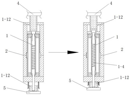
[0035] A probe assembly in this embodiment includes a probe 1 , a probe socket 2 and a support frame 3 .
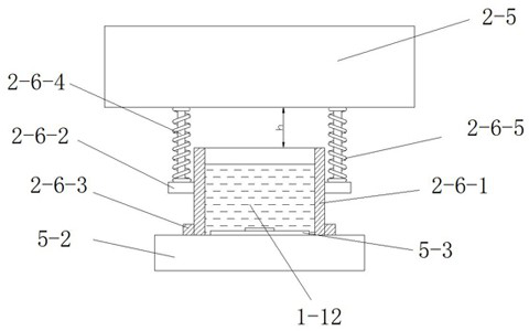
[0036] The probe 1 is arranged in the probe socket 2, and the probe socket 2 is fixed between the object 4 to be measured and the test member 5 through the support frame 3, and the lower end surface of the object 4 to be measured is connected to the first column end of the probe 1. 1-3 are electrically connected, and the second column end of the probe 1 is electrically connected with the test member 5 through the conductive fluid in the liquid holding tube 2-6-2.
[0037] The probe socket 2 can be detachably installed on the support frame 3, and the displacement of the support frame 3 is controlled by the driver to adjust the position of the probe socket 2. At the same time, the probe socket can be fixed, and the object to be measured 4 is set on It can be adjusted and fixed on the instrument to meet the fixation and movement of the object 4 to be measured.
[0038] When t...
Embodiment 2
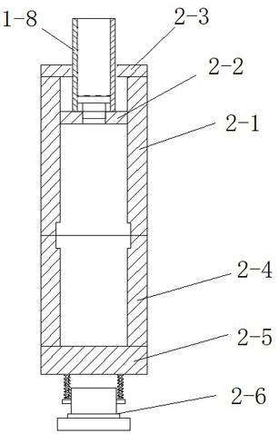
[0050] A probe socket disclosed in this embodiment includes: an upper unit 2-1, a spacer 2-2, a first cover 2-3, a lower unit 2-4, a second cover 2-5, a connection pieces 2-6.
[0051] Both the upper unit 2-1 and the lower unit 2-4 are square tubes with cuboid cavities inside to fully adapt to the shape of the columnar tube 1-1. The columnar tube 1-1 is square.
[0052] The upper unit 2-1 is provided with a spacer 2-2 inside, and the top of the upper unit 2-1 is provided with a first cover plate 2-3, and the lower port of the upper unit 2-1 is docked with the upper port of the lower unit 2-4 Forms the body of the complete probe socket. The lower end of the lower unit 2-4 is provided with a second cover plate 2-5, and the lower end of the second cover plate 2-5 is provided with a connecting piece 2-6.
[0053] The probe 1 is assembled in a cylindrical tube 1-1, and the cylindrical tube 1-1 is stably arranged in the probe socket through a positioning ring 1-2. Corresponding g...
Embodiment 3
[0061] A test method for probe components such as Figure 4 shown, including the following steps;
[0062] Step a, the point to be measured, select the electrical contact 4-1 to be measured on the object 4 to be measured for marking;
[0063] Step b, forming a closed circuit, align the funnel-shaped nozzle 1-10 with the electrical contact 4-1 to be tested by fine-tuning the support frame 3 of the probe socket, and at the same time align the sealing ring 1-11 with the bottom of the object 4 to be tested. The surface is fully attached, and the wiring board 5-2 is pushed upward by the driver, so that the lower end of the second column end 1-5 is completely against the welding pad 5-3, and reaches the upper end of the liquid holding tube 2-6-1 Abut against the lower end surface of the second cover plate 2-5, so that the lower end of the liquid holding pipe 2-6-1 and the upper end surface of the welding pad 5-3 form a closed space, so that the liquid injection forms a preliminary ...
PUM
 Abstract
Description
Claims
Application Information
 - R&D
- Intellectual Property
- Life Sciences
- Materials
- Tech Scout
- Unparalleled Data Quality
- Higher Quality Content
- 60% Fewer Hallucinations
Browse by: Latest US Patents, China's latest patents, Technical Efficacy Thesaurus, Application Domain, Technology Topic, Popular Technical Reports.
© 2025 PatSnap. All rights reserved.Legal|Privacy policy|Modern Slavery Act Transparency Statement|Sitemap|About US| Contact US: help@patsnap.com


