
A current collector provided with a micro-insurance and a lithium-ion battery pole piece containing the current collector

A current collector and microstructure technology, applied in battery electrodes, non-aqueous electrolyte battery electrodes, secondary batteries, etc., can solve problems such as low electrical and thermal conductivity, low internal resistance, reduced electrical conductivity of current collectors, and discounts on electrical conductivity, and achieve good The effect of conductivity

Active Publication Date: 2022-04-12
HEFEI GUOXUAN HIGH TECH POWER ENERGY
View PDF19 Cites 0 Cited by
  • Summary
  • Abstract
  • Description
  • Claims
  • Application Information

AI Technical Summary

Problems solved by technology

Commonly used current collectors are aluminum (positive electrode) or copper (negative electrode), which have excellent electrical conductivity and low internal resistance. However, when subjected to abnormal conditions such as violent impact, extrusion, and acupuncture, it may cause internal short circuits and internal resistance. A small current collector will generate a huge short-circuit current and release a large amount of heat instantly, which will seriously cause thermal runaway
In order to solve this problem, Chinese patent CN107437622A coats a PTC layer composed of a polymer base layer and a conductive agent on the surface of the current collector. However, although the existence of PTC can be sensitive to temperature, the polymer layer is not conductive, which affects the conductivity of the current collector. characteristics; and the patent CN104966840A generates a layer of porous alumina resistance layer on the surface of the positive electrode current collector aluminum, which eventually leads to a greatly reduced conductivity
Although the above patent documents can improve the safety performance of the battery to a certain extent, and can effectively protect the battery from thermal runaway under extreme conditions such as high temperature and high current of the battery, they all greatly reduce the electrical conductivity of the current collector, which has nothing to do with the function of the current collector. The required characteristics of excellent electrical and thermal conductivity and low internal resistance are contrary

Method used


Image

  • A current collector provided with a micro-insurance and a lithium-ion battery pole piece containing the current collector
  • A current collector provided with a micro-insurance and a lithium-ion battery pole piece containing the current collector
  • A current collector provided with a micro-insurance and a lithium-ion battery pole piece containing the current collector

Examples


Embodiment 1

[0044] First, the aluminum foil with a thickness of 10 μm is roughened, and the roughening treatment steps are:

[0045] (1) Surface cleaning: Clean the aluminum foil with ultrasonic vibration in ethanol, then soak it in 0.05mol / L lye for 3 hours; finally clean it with water;

[0046] (2) Electrochemical oxidation: The cleaned aluminum foil is electrochemically oxidized in 0.5mol / L oxalic acid solution for 5min, and its current density is 10mA / cm 2 ;

[0047] (3) Drying treatment: the treated aluminum foil is washed with deionized water and then dried.

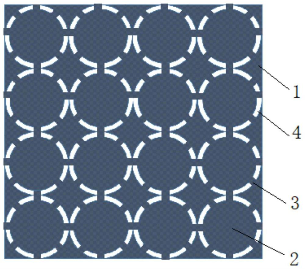
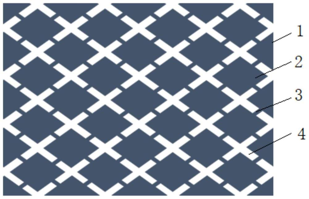
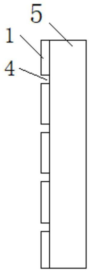
[0048]Then, a conductive aluminum coating 1 is coated on the surface of the roughened aluminum foil by vacuum evaporation, and the thickness of the conductive aluminum coating is 100 nm. The conductive aluminum coating 1 includes microstructure units 2 and contact points 3 evenly arranged on the aluminum foil; an isolation region 4 is formed between adjacent microstructure units 2, and the contact point 3 is arranged on the ...

Embodiment 2

[0051] Copper foil with a thickness of 6 μm is roughened first, and the roughening treatment steps are:

[0052] (1) Surface cleaning: ultrasonically clean the copper foil in ethanol, then soak it in 0.08mol / L lye for 2 hours; finally clean it with water;

[0053] (2) Electrochemical oxidation: electrochemically oxidize the cleaned copper foil in 0.5mol / L citric acid solution for 5min, and the current density is 15mA / cm2;

[0054] (3) Drying treatment: the treated copper foil is washed with deionized water and then dried.

[0055] The structure of the current collector is the same as in Example 1, the only difference is that a conductive copper coating is vacuum-evaporated on the copper foil substrate after roughening treatment, the thickness is 200nm, and the total area of ​​the eight contact points is the area of ​​the circular microstructure unit 10% of that; 15,000 microstructure units are provided per square meter of the surface of the copper foil substrate.

[0056] Th...

Embodiment 3

[0058] First, the aluminum foil with a thickness of 10 μm is roughened, and the roughening treatment steps are:

[0059] (1) Surface cleaning: Clean the aluminum foil with ultrasonic vibration in acetone, then soak it in 0.5mol / L lye for 0.5h; finally clean it with water;

[0060] (2) Electrochemical oxidation: The cleaned aluminum foil is electrochemically oxidized in 0.05mol / L oxalic acid solution for 20min, and the current density is 50mA / cm2;

[0061] (3) Drying treatment: the treated aluminum foil is washed with deionized water and then dried.

[0062] Then, on the surface of the aluminum foil 5, a conductive aluminum coating 1 (such as figure 2 , 3 Shown), the thickness of the conductive aluminum coating 1 is 300nm. The conductive aluminum coating 1 includes microstructure units 2 and contact points 3 uniformly arranged on the aluminum foil 5; isolation regions 4 are formed between adjacent microstructure units 2, and the contact points 3 are arranged on the isolatio...


PUM

PropertyMeasurementUnit
thicknessaaaaaaaaaa
thicknessaaaaaaaaaa
current densityaaaaaaaaaa

Abstract

The invention discloses a current collector provided with a micro-insurance, comprising a current collector base material, the surface of the current collector base material is pretreated, and a conductive metal coating is plated on the surface of the current collector base material, and the conductive metal The plating layer includes microstructure units and contact points uniformly arranged on the current collector substrate; isolation regions are formed between adjacent microstructure units, and the contact points are arranged on the isolation regions to connect adjacent microstructure units. At the same time, a lithium ion battery pole piece containing the current collector is also disclosed. In the present invention, a patterned conductive metal coating is arranged on the surface of the pretreated current collector base material by using coating technology, which maintains good conductivity and also functions as a fuse. In addition, pre-roughening or coating the PTC layer on the current collector base material effectively improves the safety performance of the battery.

Description

technical field [0001] The invention belongs to the technical field of lithium-ion battery manufacturing, and in particular relates to a current collector provided with a micro-insurance and a lithium-ion battery pole piece containing the current collector. Background technique [0002] As an important component of lithium-ion batteries, the current collector can directly affect the overall performance of the battery. It collects current in the battery to provide electronic channels to form current output and accelerate charge transfer. Therefore, the current collector itself needs to have the characteristics of excellent electrical and thermal conductivity, light weight, strong mechanical strength, low internal resistance, low cost, and stable chemical properties. Commonly used current collectors are aluminum (positive electrode) or copper (negative electrode), which have excellent electrical conductivity and low internal resistance. However, when subjected to abnormal cond...

Claims


Application Information

Patent Timeline
Patent Type & Authority Patents(China)
IPC IPC(8): H01M4/66H01M4/70H01M4/13H01M10/0525H01M4/04
CPCH01M4/667H01M4/70H01M4/13H01M10/0525H01M4/0404Y02E60/10
Inventor 李缜王启岁汪涛张江伟王晨旭杨中舒
Owner HEFEI GUOXUAN HIGH TECH POWER ENERGY
Learn More