Multi-optical port communication method, device, device and storage medium

A communication method and technology of a communication device, which are applied to the selection device, selection device, and data exchange through path configuration in a multiplexing system, can solve problems such as impracticality, conflict, and imperfect improvement methods, and achieve complete guarantees. the effect of ensuring accuracy

Active Publication Date: 2022-03-25
COMBA TELECOM SYST CHINA LTD
View PDF13 Cites 0 Cited by
  • Summary
  • Abstract
  • Description
  • Claims
  • Application Information

AI Technical Summary

Problems solved by technology

However, the premise that this method is applicable to the upper-level unit is that the lower-level unit connected to it is a device for transmission through a single optical port, and this optical port only corresponds to one of the fixed optical ports transmitted to the upper-level unit. It is only possible to change the MAC address of the next-level unit to distinguish the incoming information from each optical port, but the next-level unit is also a device for multi-optical port transmission, and the multiple optical ports of the next-level unit do not only correspond to transmission To one of the fixed optical ports of the upper-level unit, but to multiple optical ports of the upper-level unit, in this case, the upper-level unit cannot achieve multiple Optical port transmission; secondly, changing the MAC address to identify the optical port is likely to cause MAC address conflicts when multiple units are cascaded; finally, although this improved method has realized the multi-optical port transmission of the upper unit, it involves For the configuration and improvement of the lower-level unit, if the upper-level unit needs to add more connected lower-level units, it is necessary to repeat the configuration of more lower-level units. It can be seen that this improvement method is not perfect and not practical

Method used


Image

  • Multi-optical port communication method, device, device and storage medium
  • Multi-optical port communication method, device, device and storage medium
  • Multi-optical port communication method, device, device and storage medium

Examples


Embodiment 1

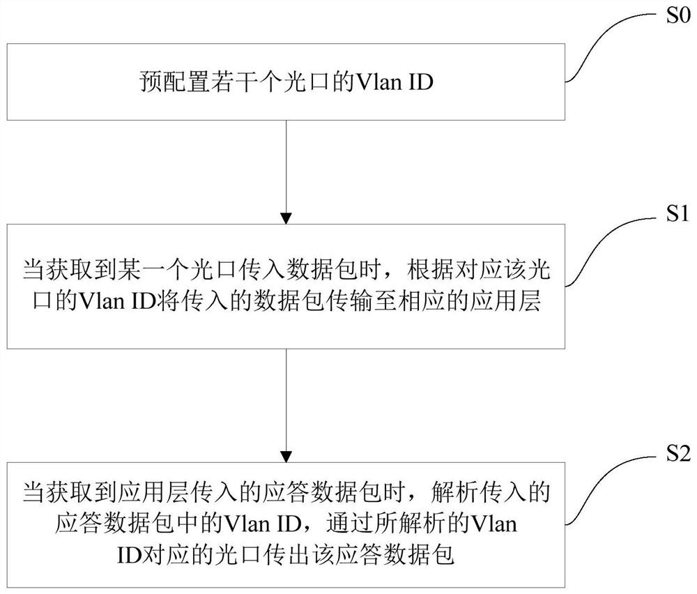
[0032] Such as figure 1 As shown, the present embodiment provides a multi-optical port communication method, and the steps include:

[0033] S0: Pre-configure the Vlan IDs of several optical ports;

[0034] Configure a unique Vlan ID for each optical port in advance, so that the Vlan ID acts as an identifier for each optical port, and forms a one-to-one mapping relationship with the corresponding optical port. Vlan ID refers to the ID used to represent different virtual local area networks. In this embodiment, configuring a unique Vlan ID for each optical port means that each optical port uses a different virtual local area network for communication, and then represents the used Vlan ID of each optical port. The IP addresses are different, so after configuring the Vlan ID, it is necessary to virtualize a network interface for each optical port, and pre-configure a unique IP address for the virtual network interface of each optical port, then the IP address of each optical por...

Embodiment 2

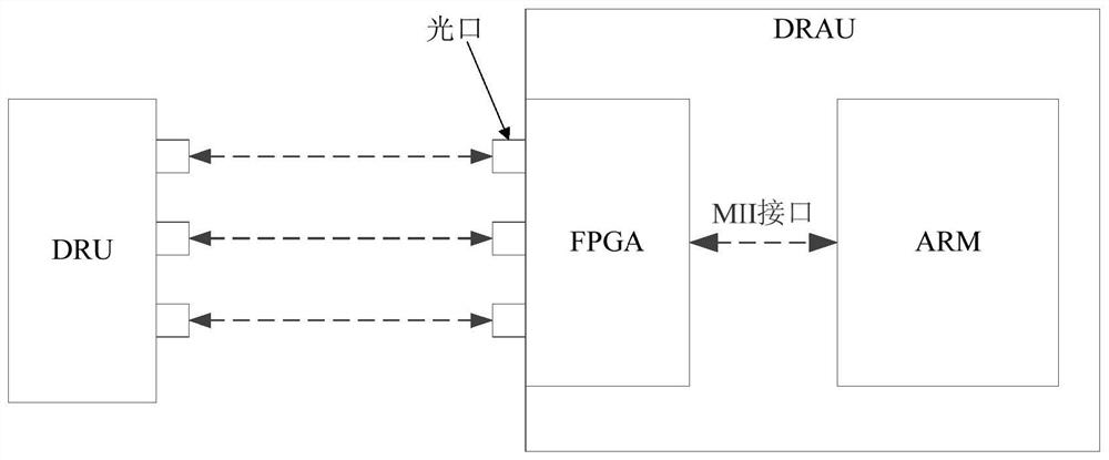
[0058] This embodiment provides a multi-optical port communication method, which is applied to a digital access unit DRAU.

[0059] Such as figure 2 As shown, the digital access unit DRAU includes an FPGA, and an ARM (serving as the CPU of the digital access unit DRAU) connected to the FPGA through the MII interface. The digital access unit DRAU and the digital remote unit DRU belong to two units in the digital remote radio system. The digital access unit DRAU is the upper-level unit of the digital remote unit DRU, and the communication between the two is connected through an optical fiber. Both are equipped with multiple optical ports (fiber optic interfaces), as an example, figure 2 Only three optical ports of the digital access unit DRAU and the digital remote unit DRU are shown.

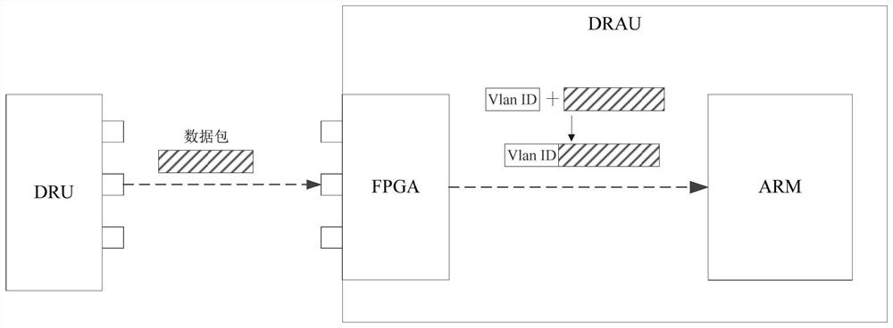
[0060] When the method is applied to the digital access unit DRAU, the ARM of the digital access unit DRAU performs the following steps:

[0061] S0: Pre-configure the Vlan IDs of several op...

Embodiment 3

[0086] This embodiment provides a multi-optical port communication device, including an optical port information processing module, used to preset Vlan IDs of several optical ports (optical fiber interfaces), wherein several optical ports belong to any device / The unit can also be the optical port provided by the multi-optical port communication device of this embodiment itself, which means that the multi-optical port communication device can be used to process the multi-optical port communication data transmission of other equipment / units, and can also be used for its own Multi-port communication data transmission.

[0087] The optical port information processing module is also used to transmit the incoming data packet to the corresponding application layer according to the Vlan ID corresponding to the optical port when obtaining the incoming data packet from a certain optical port.

[0088] Preferably, the optical port information processing module is specifically configured...


PUM


Abstract

The invention discloses a multi-optical port communication method, device, device and storage medium, wherein the method includes: pre-configuring the Vlan IDs of several optical ports; The Vlan ID of the interface is used to transmit the data packet to the corresponding application layer. Through the Vlan ID corresponding to the optical port, the data packet can be distinguished from the incoming data packets of other optical ports. Since the frequency bands of the signals transmitted by different optical ports are different, the incoming data packets of different optical ports need to carry out information The interactive application layer will also be different, and the data packet can be transmitted to the application layer corresponding to the optical port for information interaction through the unique Vlan ID; the method provided by the present invention realizes multiple For optical port communication, there is no need to configure or modify any peer or next-level unit / device, and the MAC address of any unit / device is not changed during the entire transmission process of the data packet, avoiding the problem of MAC address conflicts.

Description

technical field [0001] The present invention relates to the field of optical fiber communication, more specifically, to a multi-optical port communication method, device, equipment and storage medium. Background technique [0002] In the communication system, the digital radio remote system GRRU (GSM Digital Remote RF Units) uses software radio technology to digitize the signal of the GSM Um port, transmits it to the remote end through optical fiber, and uses the remote radio frequency unit to regenerate and amplify the base station signal. Remote coverage wireless network coverage equipment. GRRU is a product that successfully applies RRU technology widely used in 3G to GSM system, and provides an effective solution for network coverage engineering and optimization. Among them, the digital remote radio system includes a digital access unit DRAU and a digital remote unit DRU. The digital access unit DRAU directly couples the base station signal, and transmits the signal to ...

Claims


Application Information

Patent Timeline
Patent Type & Authority Patents(China)
IPC IPC(8): H04L12/46H04L1/00H04L61/5014H04Q11/00H04L61/5046
CPCH04L12/4645H04L1/0061H04Q11/0067H04L61/5046H04L61/5014
Inventor 李秉荣方彬浩陈炳锐
Owner COMBA TELECOM SYST CHINA LTD
Why Eureka
Try Eureka