Sliding type silo cantilever tripod structure and mounting method

A tripod and sliding technology, applied in the direction of housing structure support, housing structure support, scaffolding supported by housing structure, etc., can solve the problems of inconvenient and convenient dismantling, high positioning requirements, size deviation, etc., and achieve convenient and fast installation and dismantling. , beautiful appearance, simple structure effect

Inactive Publication Date: 2021-02-05
CHINA FIRST METALLURGICAL GROUP
View PDF9 Cites 0 Cited by
  • Summary
  • Abstract
  • Description
  • Claims
  • Application Information

AI Technical Summary

Problems solved by technology

[0002] There are many large-diameter storage silos in the grain industry. At present, the construction of the cantilevered platform on the top of the silo almost uses pre-embedded iron parts on the silo wall, and then fixes it by welding or fixes it on the silo wall. Suspending the tripod hanger, the two methods have certain disadvantages, and there are great difficulties in the later dismantling. Because the height of the overhanging platform of the silo wall is high, the removal of the tripod hanger is all high-altitude operations. No matter whether welding or suspension is used, the removal Oxygen cutting must be used for cutting and dismantling. When cutting tripods, it takes a certain amount of time to work at heights. The dismantling is extremely inconvenient and inconvenient, and black marks will be left on the warehouse wall after resection. It must be polished and repaired with cement slurry later. To ensure that it is consistent with the color of the warehouse wall
In addition, when installing the tripod hanger, due to some deviations in the pre-embedded dimensions, if you want to change the position of the tripod hanger, you must re-embed or change it in other ways, which requires very high pre-embedded positioning

Method used


Image

  • Sliding type silo cantilever tripod structure and mounting method
  • Sliding type silo cantilever tripod structure and mounting method
  • Sliding type silo cantilever tripod structure and mounting method

Examples


Embodiment Construction

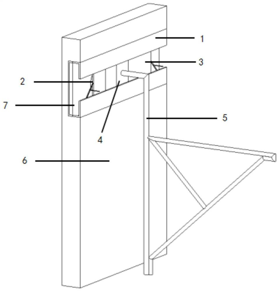
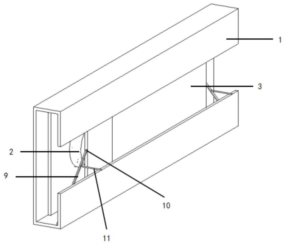
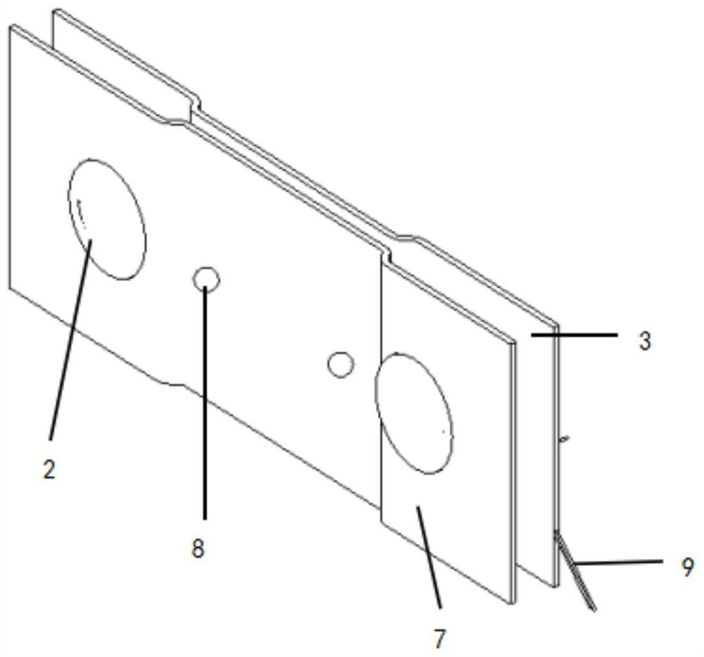
[0033] Below in conjunction with accompanying drawing and specific embodiment the present invention will be described in further detail:

[0034] The sliding type silo cantilevered tripod structure designed by the present invention includes a C-shaped card slot 1, a sliding connection mechanism and a braking device for restricting the movement of the sliding mechanism. The fixed end of the overhanging tripod 5 is provided with a hanging plate 4, The tripod hanger 5 is integrated with the hanging plate 4, and the connection is firm; the C-type card slot 1 is pre-buried in the silo wall 6; the sliding connection mechanism includes an elastic baffle 3, a spring 2, and a sliding baffle 7, and the spring 2 is arranged on the Between the elastic baffle 3 and the sliding baffle 7 arranged oppositely, the elastic baffle 3 is provided with an indented groove matched with the hanging plate 4; the contact surface between the sliding baffle 3 and the C-shaped slot is provided with a ball 8...


PUM


Abstract

The invention relates to a sliding type silo cantilever tripod structure and a mounting method. The sliding type silo cantilever tripod structure comprises a C-shaped clamping groove, a sliding connection mechanism and brake devices used for limiting the movement of a sliding mechanism, a hanging plate is arranged at the fixed end of a cantilever tripod, and the C-shaped clamping groove is pre-buried in a silo wall; the sliding connection mechanism comprises a springing baffle, a spring and a sliding baffle, wherein the spring is arranged between the springing baffle and the sliding baffle which are oppositely arranged, and balls are arranged on the contact surface of the sliding baffle and the C-shaped clamping groove; and by rotating the silo cantilever three-legged hanging bracket, thespring in the device is started accordingly, and the purpose of mounting the silo cantilever three-legged hanging bracket is achieved. The structure is completely made of common materials and is simple and practical, and the three-legged hanging bracket can freely slide in the C-shaped channel steel and can be freely adjusted according to the actual size on site.

Description

technical field [0001] The invention relates to the field of granary construction, in particular to a sliding type silo cantilevered tripod structure and an installation method. Background technique [0002] There are many large-diameter storage silos in the grain industry. At present, the construction of the cantilevered platform on the top of the silo almost uses pre-embedded iron parts on the silo wall, and then fixes it by welding or fixes it on the silo wall. Suspending the tripod hanger, the two methods have certain disadvantages, and there are great difficulties in the later dismantling. Because the height of the overhanging platform of the silo wall is high, the removal of the tripod hanger is all high-altitude operations. No matter whether welding or suspension is used, the removal Oxygen cutting must be used for cutting and dismantling. When cutting tripods, it takes a certain amount of time to work at heights. The dismantling is extremely inconvenient and inconven...

Claims


Application Information

Patent Timeline
Patent Type & Authority Applications(China)
IPC IPC(8): E04G3/28E04G5/04E04G5/00
CPCE04G3/28E04G5/007E04G5/045E04G2003/283
Inventor 余洋武杰王盛宇张豪
Owner CHINA FIRST METALLURGICAL GROUP
Why Eureka
Try Eureka