
Coaxial heat exchanger, evaporator, condenser and refrigerating system

A refrigeration system and heat exchanger technology, applied in the fields of condensers, refrigeration systems, evaporators, and coaxial heat exchangers, can solve the problems of low refrigerant density, low heat transfer coefficient, large pressure drop, etc. The effect of large thermal coefficient, low heat transfer coefficient and small heat transfer area

Pending Publication Date: 2021-02-05
HANGZHOU SHENSHI ENERGY CONSERVATION TECH
View PDF0 Cites 0 Cited by
  • Summary
  • Abstract
  • Description
  • Claims
  • Application Information

AI Technical Summary

Problems solved by technology

In the second half, the density is small, the flow rate is high, and the pressure drop is large, which does not change with the change of the refrigerant; as a condenser, the refrigerant is also a single flow, and the area of ​​the refrigerant side channel is the same before and after the refrigerant in the heat exchange process of the heat exchanger , but the refrigerant has low density, high flow velocity, and large pressure drop in the first half, and the second half has high density, low flow velocity, and low heat transfer coefficient, which does not change with the change of refrigerant, that is, the coaxial heat transfer in the prior art The heat exchanger is not adapted to the characteristics of the different states of the refrigerant, and the heat transfer effect of the heat exchanger cannot be fully utilized

Method used


Image

  • Coaxial heat exchanger, evaporator, condenser and refrigerating system
  • Coaxial heat exchanger, evaporator, condenser and refrigerating system
  • Coaxial heat exchanger, evaporator, condenser and refrigerating system

Examples


Embodiment 1

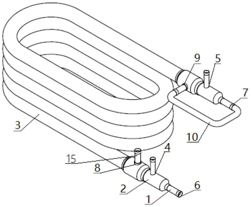
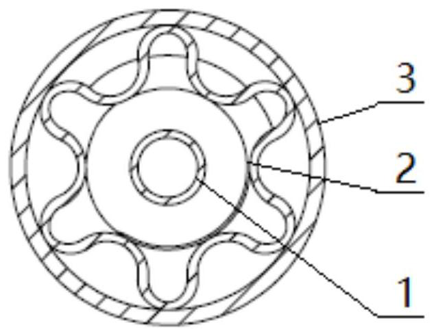
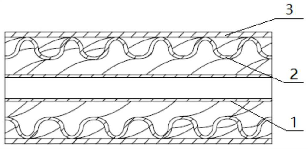
[0036] This embodiment provides a coaxial heat exchanger, including at least one connecting pipeline 10, at least one brine pipeline 2 and multiple refrigerant pipelines, and the brine pipeline 2 and the refrigerant pipeline are arranged coaxially , the inner side and the outer side of the brine pipeline 2 are respectively provided with refrigerant pipelines, and the refrigerant pipelines are connected by connecting pipelines 10 . Wherein the connecting pipeline 10, the brine pipeline 2 and the refrigerant pipeline can be copper pipelines or stainless steel pipelines or nickel-white copper pipelines or steel pipelines or titanium pipelines or pipelines of other materials; The overall pipeline of the heater can be as follows figure 1 The shown U-shaped structure or square structure or circular mosquito-repellent-repellent incense structure or double-circle structure or other shaped structures are arranged.

[0037] Such as figure 1As shown, in this embodiment, there are two r...

Embodiment 2

[0043] This embodiment provides an evaporator for evaporating and heat-exchanging refrigerant in a refrigeration system, including the coaxial heat exchanger in Embodiment 1, and using the coaxial heat exchanger for refrigerant and brine heat exchange.

Embodiment 3

[0045] This embodiment provides a condenser for condensing and heat-exchanging refrigerant in a refrigeration system, including the coaxial heat exchanger in Embodiment 1, and using the coaxial heat exchanger for refrigerant and brine heat exchange.


PUM


Abstract

The invention discloses a coaxial heat exchanger, an evaporator, a condenser and a refrigerating system. The coaxial heat exchanger comprises at least one connecting pipeline, at least one secondary refrigerant pipeline and a plurality of refrigerant pipelines, wherein the secondary refrigerant pipeline and the refrigerant pipelines are coaxially arranged, the refrigerant pipelines are arranged onthe inner side and the outer side of the secondary refrigerant pipeline respectively, and the refrigerant pipelines are connected through the connecting pipeline. A refrigerant enters the other refrigerant pipeline from one refrigerant pipeline and always exchanges heat with a secondary refrigerant in the secondary refrigerant pipeline, so that a mixed process instead of a single process in the prior art is realized; and through the strengthening effect of the mixed process of the coaxial heat exchanger, the flow velocity change of the refrigerant in the heat exchanger is increased, the turbulence level is increased, and the heat exchange coefficient and the heat exchange amount of the whole heat exchanger are increased.

Description

technical field [0001] The invention relates to the technical field of heat exchange of a refrigeration system, in particular to a coaxial heat exchanger, an evaporator, a condenser and a refrigeration system. Background technique [0002] The coaxial heat exchanger is composed of an inner tube and an outer tube. The hot and cold fluids flow in the inner tube and the annulus between the inner tube and the outer tube respectively for heat transfer. The coaxial heat exchanger has pressure resistance, shock resistance, and is not easy to deform. , not easy to block, smooth oil return and other advantages. [0003] The coaxial heat exchanger in the prior art is used as an evaporator, and the refrigerant has a single flow. During the heat exchange process of the refrigerant in the heat exchanger, the area of ​​the refrigerant side channel is the same before and after, but the density of the refrigerant in the first half is high, and the flow rate is low. Low heat transfer coeffi...

Claims


Application Information

Patent Timeline
Patent Type & Authority Applications(China)
IPC IPC(8): F25B39/02F25B39/04F28D7/10F28D7/14
CPCF25B39/02F25B39/04F25B2339/02F25B2339/04F25B2500/09F28D7/103F28D7/14
Inventor 赵博杨祯杰蔡锡民赵凯凯肖康王小汉吕志锡石景祯
Owner HANGZHOU SHENSHI ENERGY CONSERVATION TECH
Features
  • Generate Ideas
  • Intellectual Property
  • Life Sciences
  • Materials
  • Tech Scout
  • Unparalleled Data Quality
  • Higher Quality Content
  • 60% Fewer Hallucinations
Learn More