Practical shear member bearing capacity test device

A test device and the technology of shearing parts, which are applied in the field of practical shearing part bearing capacity test devices, can solve the problems of lack of reference objects for measuring deformation and poor experimental accuracy, etc.

Active Publication Date: 2021-02-05
HENAN UNIVERSITY +1
View PDF9 Cites 0 Cited by
  • Summary
  • Abstract
  • Description
  • Claims
  • Application Information

AI Technical Summary

Problems solved by technology

[0006] Aiming at the defects and problems existing in the existing equipment, the present invention provides a practical test device for the bearing capacity of the shear parts, which effectively solves the problem in the existing equipment that only a single load can b

Method used


Image

  • Practical shear member bearing capacity test device
  • Practical shear member bearing capacity test device

Examples


Embodiment 1

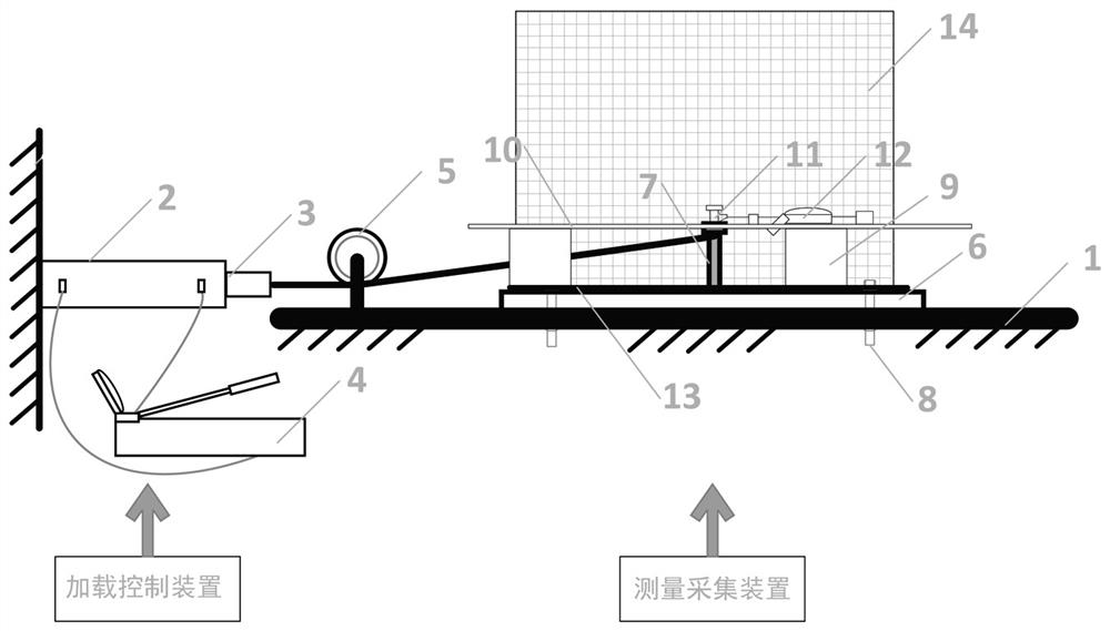
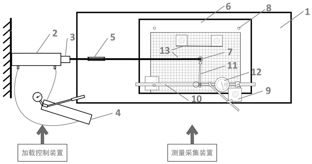
[0020] Embodiment 1: This embodiment aims to provide a practical test device for the bearing capacity of shear members, and provides an effective test loading measurement device for studying the mechanical properties of individual shear members. A single load can be applied to judge the bending deformation of the intermediate shear parts, and there is no reference object for measuring the deformation during the test process, and only the naked eye observation of the test personnel results in poor test accuracy. This embodiment provides an operation Simple, high precision, and two reference objects are set in the horizontal and vertical directions to mark its effective displacement.

[0021] Specifically, such as Figure 1-2 As shown, a practical test device for the bearing capacity of shear members includes a loading control device and a measurement acquisition device; wherein the load control device is used to apply loading force to the shear member, and the measurement acqui...

Embodiment 2

[0034] Embodiment 2: This embodiment is basically the same as Embodiment 1, the difference is that this embodiment further limits the way of setting collection points.

[0035] The collection point is provided with an installation hole, a laser emitting head is fixed in the turning hole, and a detection head is arranged on the back of the vertical coordinate paper, and the detection head can collect the path and displacement of the laser emission head.

[0036] In this embodiment, a laser emitting head is set at the collection point. The laser emitting head is small in size and light in weight and has little impact on the test of the shearing capacity. At the same time, it can emit laser light on the vertical coordinate paper, and the laser is shot on the coordinate paper. It is convenient for the test personnel to make dots on the coordinate paper, and at the same time, the detection head can record the path walking image of the laser displacement, and extract its walking path...

Embodiment 3

[0038] Embodiment 3: This embodiment is basically the same as Embodiment 1, the difference is that this embodiment further explains the structure of the pointer.

[0039] The pointer points to the collection point in the initial state. With the displacement of the collection point, the pointer can be driven to slide in the guide rail. In order to facilitate the identification of the location of the collection point, a reference rod is vertically set at the end of the pointer. When moving the pointer, the reference rod and The corresponding position of the collection points can indicate that the pointer has moved in place, and the precise displacement can be obtained through the reading of the dial indicator.

[0040] In the present invention, the piston rod of the jack is connected to the fixed pulley through a steel strand, and the other end is connected to the outer end of the shear member. When the piston rod moves in the reverse direction, it drives the shearing parts, so ...


PUM


Abstract

The invention discloses a practical shear-resistant part bearing capacity test device. The device comprises a loading control device and a measurement acquisition device; wherein the loading control device comprises a hydraulic traction rod, a steel strand and a guide wheel; the measurement and acquisition device comprises a horizontal acquisition unit and a vertical acquisition unit; the horizontal acquisition unit comprises a pointer, a guide rail, a dial indicator and horizontal coordinate paper; the guide rail is fixed above the test bed or the additional steel plate in the horizontal direction and corresponds to the collection point of the anti-shearing piece, the pointer is arranged on the guide rail in a sleeving mode, the tail end of the pointer is right opposite to the collectionpoint, and the contact of the dial indicator abuts against the end of the pointer; the vertical acquisition unit comprises a vertical plate and vertical coordinate paper; and the vertical coordinate paper is arranged on the vertical plate. The test device provides a new detection mode for measuring the ultimate shear bearing capacity and effective deformation of the shear member, has the advantages of accurate data, strong practicability and convenient operation, and is a great innovation of the bearing capacity test of the shear member.

Description

technical field [0001] The invention belongs to the technical field of civil engineering, and in particular relates to a practical test device for the bearing capacity of shear parts. Background technique [0002] Since the 1920s, composite components and structures have been continuously recognized and promoted by the engineering community. At the same time, the research work on composite components and structures is also increasing and deepening, and the advantages of the more common prefabricated steel structures and concrete composite components and structures are gradually revealed. [0003] In the prefabricated steel structure and concrete composite components and structures, the steel structure has the characteristics of convenient connection, good tensile performance, and is conducive to factory construction. Concrete has the characteristics of low cost, easy to obtain materials, good fire resistance, and good compression resistance. The prefabricated steel structu...

Claims


Application Information

Patent Timeline
IPC IPC(8): G01N3/24G01N3/06
CPCG01N3/24G01N3/062G01N3/068G01N2203/0025G01N2203/0605G01N2203/0641G01N2203/0676
Inventor 马少春娄元元李娜娜鲁冰鲍鹏王辉
Owner HENAN UNIVERSITY
Why Eureka
Try Eureka