Generator stator cooling water loop drying system and method

A generator stator and drying system technology, applied in the manufacture of motor generators, drying gas arrangement, cooling fluid circulation device, etc., can solve the problems of difficult monitoring of the working process, large demand for human resources, and reduction of drying time, etc., to achieve Improve the efficiency of water blowing drying, improve drying efficiency, and reduce drying time

Pending Publication Date: 2021-02-05
芜湖发电有限责任公司
View PDF0 Cites 1 Cited by
  • Summary
  • Abstract
  • Description
  • Claims
  • Application Information

AI Technical Summary

Problems solved by technology

[0010] In order to solve the above technical problems, a generator stator cooling water circuit drying system and method are provided. This technical solution solves the problems of difficult monitoring of the application workflow of the current technology and method, large demand for human resources, and easy generation of equipment hidden dangers. The system and method can realize full-automatic or semi-automatic pressure blowing function, reduce labor intensity, reduce drying time, and have compressed air heating function to improve blowing and drying efficiency

Method used


Image

  • Generator stator cooling water loop drying system and method
  • Generator stator cooling water loop drying system and method
  • Generator stator cooling water loop drying system and method

Examples


Embodiment Construction

[0047] The following description serves to disclose the present invention to enable those skilled in the art to carry out the present invention. The preferred embodiments described below are only examples, and those skilled in the art can devise other obvious variations.

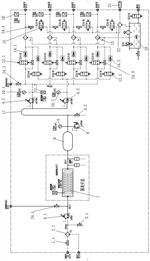
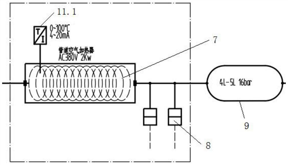
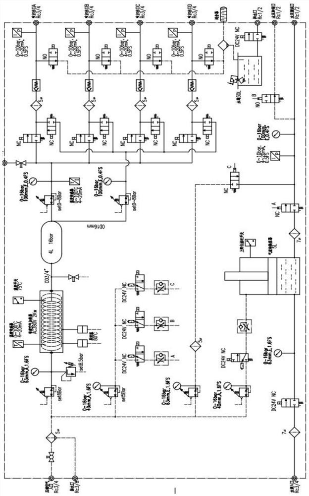
[0048] see figure 1 , figure 2 , image 3 and Figure 4 , the drying system includes a purge cabinet, which is provided with a purge circuit connected to the generator stator bar pipeline, and the purge circuit includes:

[0049] The first pipeline, the inlet end of the first pipeline is fed with purge gas, the purge gas is the gas source, in this embodiment, the purge gas adopts compressed air source or inert gas source, and the inert gas can be selected For high-purity nitrogen or other inert gases, the first pipeline is connected in series with an intake stop valve 1.1 and a first filter 2.1, and the intake stop valve 1.1 is located at the front end of the first filter 2.1.

[0050] Heating device, ...


PUM


Abstract

The invention relates to the field of generators, and concretely relates to a generator stator cooling water loop drying system and method. The generator stator cooling water loop drying system comprises a purging cabinet, and a purging loop communicated with a generator stator bar pipeline is arranged in the purging cabinet. The purging loop comprises: a first pipeline, wherein purging gas is introduced into the gas inlet end of the first pipeline, a gas inlet stop valve and a first filter are connected to the first pipeline in series, and the gas inlet stop valve is located at the front endof the first filter; a heating device, wherein the gas inlet end of the heating device is connected with the gas outlet end of the first pipeline, and the heating device heats the purge gas entering the heating device; a second pipeline, wherein the gas inlet end of the second pipeline is connected with the gas outlet end of the heating device; and a plurality of third pipelines, wherein the gas inlet end of each third pipeline is connected with the gas outlet end of the second pipeline. The full-automatic or semi-automatic pressure blowing function can be achieved, the drying time is shortened, meanwhile, the compressed air heating function is achieved, and the water blowing and drying efficiency is improved.

Description

technical field [0001] The invention relates to the field of generators, in particular to a drying system and method for a generator stator cooling water circuit. Background technique [0002] According to the requirements of the national "Preventive Test Regulations for Electric Power Equipment", synchronous generators with a capacity of 6000kW and above must undergo stator winding leakage current and DC withstand voltage tests before and after overhaul. At present, the water collection pipes on both sides of the stator winding steam and excitation of large generators are directly grounded, which requires that the water in the stator winding water circuit must be blown clean and dry before the stator winding leakage current and DC voltage withstand test are performed on the generator. . [0003] How to clean the water in the stator winding water circuit of this type of generator has always been a big headache for the maintenance unit. At present, the process of blowing wat...

Claims


Application Information

Patent Timeline
Patent Type & Authority Applications(China)
IPC IPC(8): H02K15/12F26B21/00F25D17/02
CPCF25D17/02F26B21/001H02K15/12
Inventor 李治江军王巍松王芳勇刘爱武李秀平翟永祥王宏伟曹志贵胡锦林
Owner 芜湖发电有限责任公司
Why Eureka
Try Eureka