PWM dimming type LED light-emitting system capable of avoiding inductive current overshoot

A technology of inductive current and lighting system, applied in the field of LED dimming, can solve problems such as insufficient current resistance, insufficient response speed of the switching system, loss of adjustment function, etc.

Active Publication Date: 2021-02-05
WUXI VOCATIONAL & TECHN COLLEGE
View PDF6 Cites 1 Cited by
  • Summary
  • Abstract
  • Description
  • Claims
  • Application Information

AI Technical Summary

Problems solved by technology

However, when the rising edge of the PWM signal comes, the DRV signal that triggers the driver output of the Boost circuit is turned on, and at the same time the load current ILED is turned on, and the current of the inductor L rises from zero. At the beginning, the current IL of the inductor L is low, due to the inductance The current provided by L to the LED load is not large enough, so the VOUT at both ends of the LED load will drop, and the circuit regulation will increase the duty cycle. Because the response speed of the switching system is not enough, the current IL of the inductor L will be adjusted back after exceeding the need. phenomenon, that is, the occurrence of figure 2 The overshoot phenomenon shown, which will cause the inductance with insufficient current resistance to be saturated and damage the inductance L, losing its regulation function

Method used


Image

  • PWM dimming type LED light-emitting system capable of avoiding inductive current overshoot
  • PWM dimming type LED light-emitting system capable of avoiding inductive current overshoot
  • PWM dimming type LED light-emitting system capable of avoiding inductive current overshoot

Examples


Embodiment Construction

[0025] The specific embodiments of the present invention will be further described below in conjunction with the accompanying drawings.

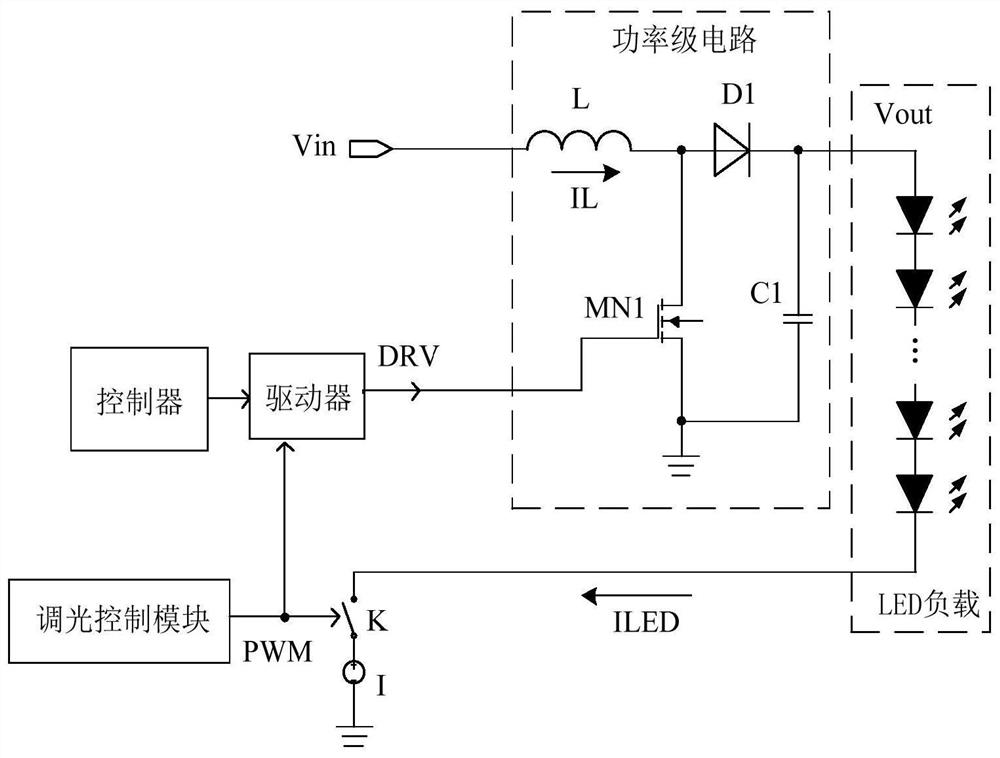
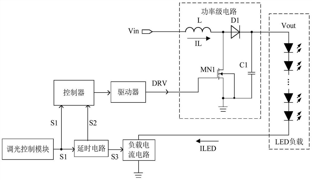
[0026] This application discloses a PWM dimming LED lighting system that avoids inductor current overshoot, please refer to image 3 The system architecture diagram shown also includes the power stage circuit and LED load. The power stage circuit mainly includes inductor L, switch tube MN1, capacitor C1 and diode D1. The circuit structure of the power stage circuit and LED load is similar to the conventional one. This application No longer. The system also includes a dimming control module, a delay circuit, a load current circuit, a driver and a controller, and the power stage circuit, the LED load and the load current circuit form a series circuit.

[0027] The dimming control module is connected to the controller and the delay circuit and outputs PWM signal S1. The output terminals of the delay circuit are respectively connected to the co...


PUM


Abstract

The invention discloses a PWM dimming type LED light-emitting system capable of avoiding inductive current overshoot, and relates to the technical field of LED dimming. When a controller detects a rising edge of a PWM signal provided by a dimming control module, the controller controls a driver to output a driving signal with a first duty ratio to a power stage circuit; then, a current of an inductor in the power stage circuit rises in a no-load-current state until the rising edge of a PWM delay signal delayed by the delay circuit for a preset duration arrives, and the PWM delay signal is switched to a stable state; a driving signal of the power stage circuit outputs several pulse signals at first with a high duty ratio; and finally, the load current is turned on after a certain delay, andthe PWM delay signal is turned off after a certain delay. Therefore, the inductor can be firstly increased to a certain degree in a no-load current state, the output voltage cannot be reduced due tothe fact that the current of the inductor does not reach a stable value, and the current overshoot phenomenon of the inductor can be effectively avoided.

Description

technical field [0001] The invention relates to the technical field of LED dimming, in particular to a PWM dimming LED lighting system that avoids the overshoot of inductive current. Background technique [0002] The LED lighting system has two dimming control methods, analog dimming and digital dimming. Digital dimming is also called PWM dimming, which can achieve a relatively wide dimming range, and the current of the LED load is fixed every time it is turned on. The LED has no color shift, so the PWM dimming control method is generally used in the industry at present. [0003] The current PWM dimming LED lighting system generally uses a switching power supply for power supply. The commonly used circuit structure is as follows: figure 1 As shown, it mainly includes the power stage circuit (Power Stage), LED load (Led Load), switch K and current source I connected in series, and the dimming control module (PWM dimming) generates a PWM signal to the driver Driver and contro...

Claims


Application Information

Patent Timeline
Patent Type & Authority Applications(China)
IPC IPC(8): H05B45/325
CPCH05B45/325Y02B20/40
Inventor 马忠亮崔安芳胡俊平
Owner WUXI VOCATIONAL & TECHN COLLEGE
Why Eureka
Try Eureka