Transmission device for a hybrid vehicle

A motor vehicle and torque transmission technology, which is applied in the direction of hybrid vehicles, power devices, air pressure power devices, etc., can solve problems such as the complexity of transmission device installation, achieve radial and axial compactness, reduce floor space, and effectively Contributes to the effect of axial and radial compactness

Pending Publication Date: 2021-02-05
VALEO EMBRAYAGES SAS
View PDF8 Cites 0 Cited by
  • Summary
  • Abstract
  • Description
  • Claims
  • Application Information

AI Technical Summary

Problems solved by technology

One problem with this type of architecture is the installation complexity of the transmission

Method used


Image

  • Transmission device for a hybrid vehicle
  • Transmission device for a hybrid vehicle

Examples


Embodiment Construction

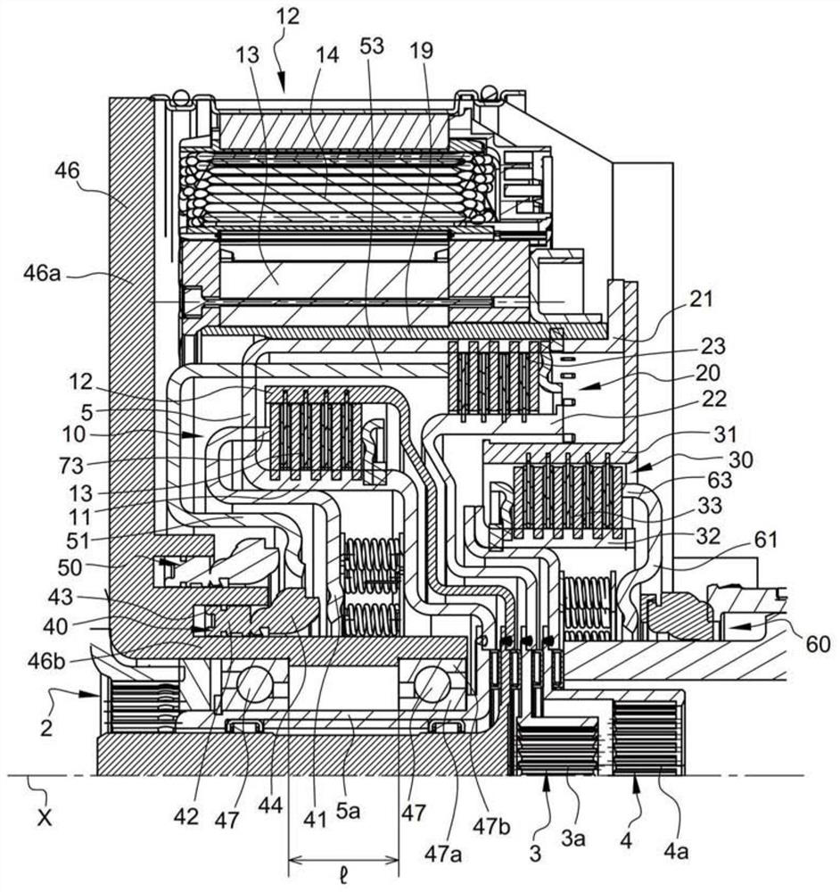
[0062] refer to figure 1 , shows a torque transmission device 1 comprising:

[0063] - a torque input element 2 which rotates about an axis of rotation X and is rotatably coupled to the crankshaft of an internal combustion engine (not shown),

[0064] - a first torque output member 3, rotatably coupled to a first input shaft of a gearbox (not shown),

[0065] - second torque output member 4, rotatably coupled to the second input shaft of the gearbox (not shown), and

[0066] In the example considered, the second output element 4 is arranged parallel to the first output element 3 in the direction of torque transmission. Each of these elements rotates about the axis of rotation X of the device.

[0067] The first output element 3 and the second output element 4 respectively include a first output interface 3a and a second output interface 4a, and the inner circumferences of the first output interface 3a and the second output interface 4a are splined and can be connected with ...


PUM


Abstract

The invention relates to a torque transmission device (1), comprising: a torque input element (2), a first torque output element (3), a rotating electric machine (12) comprising a rotor (13), an intermediate element (5) defining a rotor support, an actuating member (40) with a rotating stop, associated with the input clutch (10), a protective casing (46) arranged to at least partially envelop thetorque input element (2), the torque output element (3), the rotating electric machine (12), the intermediate element (5) and the actuating element (40), and at least one rolling bearing member (47) arranged radially between the intermediate element (5) and the protective casing (46), in which the input clutch (10), the actuating member (40) associated with the input clutch (10) and the at least one rolling bearing member (47) succeed one another radially towards the axis (X).

Description

technical field [0001] The invention relates to the field of transmissions for motor vehicles. The invention relates in particular to a torque transmission device arranged in a drive train of a motor vehicle, between an internal combustion engine and a gearbox. [0002] The invention relates in particular to a torque transmission for a hybrid vehicle, in which a rotary electric machine is arranged in a drive train. Background technique [0003] A transmission assembly arranged between a gearbox and an internal combustion engine is known in the prior art, the transmission assembly comprising a rotating electrical machine and a clutch on the engine side, which couples the crankshaft of the internal combustion engine in rotation to the rotor of the rotating electrical machine . Therefore, it is possible to shut down the internal combustion engine every time the vehicle stops, and to restart the internal combustion engine using the rotary electric machine. The rotating electr...

Claims


Application Information

Patent Timeline
Patent Type & Authority Applications(China)
IPC IPC(8): B60K6/48B60K6/387B60K6/405
CPCB60K6/387B60K6/405B60K6/48B60K2006/4825F16D25/082F16D25/10F16D2021/0661Y02T10/62
Inventor T.吉诺特J-F.布加德
Owner VALEO EMBRAYAGES SAS
Why Eureka
Try Eureka