System for storing compressed fluid

A storage system, a technology for compressing fluids, used in fluid handling, equipment loaded into pressure vessels, gas/liquid distribution and storage, etc.

Pending Publication Date: 2021-02-05
AUGWIND LTD
View PDF2 Cites 2 Cited by
  • Summary
  • Abstract
  • Description
  • Claims
  • Application Information

AI Technical Summary

Problems solved by technology

Additionally, they require a high level of maintenance and must comply with many safety regulations

Method used


Image

  • System for storing compressed fluid
  • System for storing compressed fluid
  • System for storing compressed fluid

Examples


Embodiment Construction

[0034] The principles and operation of an underground compressed gas storage system according to the present invention may be better understood with reference to the drawings and accompanying descriptions. It should be understood that these drawings are given for purposes of illustration only and are not meant to be limiting. It should be noted that for the sake of clarity, the figures illustrating various examples of the system of the present invention are not drawn to scale and are not to scale. Throughout the description of the present invention, the same reference numerals and alphabetic characters are used to identify those components that are common to the hydropneumatic energy storage systems and components thereof shown in the drawings. Provides a constructed example for the selected element. Those skilled in the art will appreciate that many of the examples provided have suitable alternatives that may be utilized.

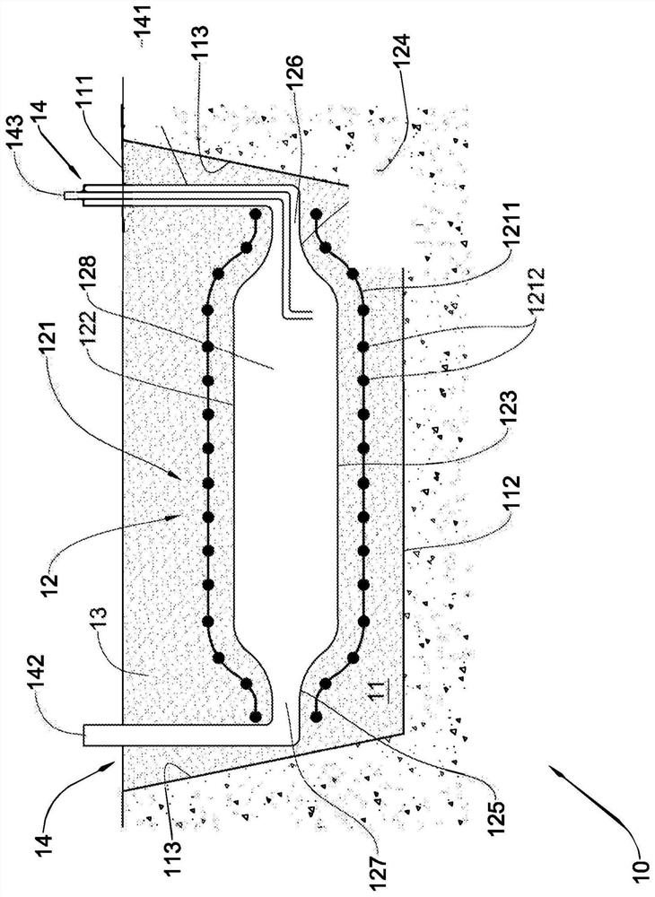
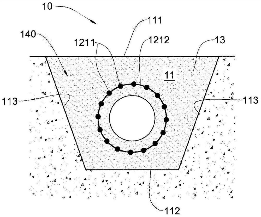
[0035] refer to Figure 1A and Figure 1B , respe...


PUM


Abstract

A storage system for storing compressed fluid is described. The system includes an excavation made in the ground, a balloon arrangement mounted within the excavation. The balloon arrangement includesa rebar cage and an inflatable balloon arranged within the rebar cage. The inflatable balloon has a middle portion and two end portions. One end portion includes a balloon inlet port, whereas the other end portion includes a balloon outlet port. The system also includes a filling material fully surrounding the inflatable balloon and configured for providing further reinforcement in conjunction with the rebar cage to the inflatable balloon, and for anchoring the inflatable balloon to the excavation. The system also includes a gas pipe assembly including an inlet gas pipe coupled to the ballooninlet port for filling the inflatable balloon with compressed fluid, and an outlet gas pipe coupled to the balloon output port for releasing the compressed fluid.

Description

technical field [0001] The present invention relates generally to systems for storing and utilizing compressed fluids, and more particularly to systems for storing compressed fluids underground and later utilizing them as energy. Background technique [0002] It is well known that compressed gases can be stored and used for many purposes. For example, stored compressed gas can be used in the glass and plastic container industry. However, due to the nature of the operation of injection molding machines using compressed air, the consumption of compressed air in glass and plastic container production plants is irregular. Each injection machine requires a small burst of high-pressure air every few seconds (one burst per injection). When several such machines are arranged in a production line, the air consumption curve is unstable and irregular. A typical plant includes a compressor train where an electric compressor compresses some gas, such as air. Due to the erratic and ir...

Claims


Application Information

Patent Timeline
Patent Type & Authority Applications(China)
IPC IPC(8): F03D9/17B65G5/00F17C1/00F17C1/02
CPCE04H7/18B65G5/00F17C1/007F17C2221/031F17C2201/054F17C2203/0685F17C2203/0639F17C2270/0147F17C2209/221F17C2203/0617F17C2223/0123F17C2201/035F17C2203/012F17C2201/018F17C2223/013F17C2205/0126F17C2205/0107E04H7/14Y02E70/30F17C5/00E04B1/30
Inventor O·尤格夫
Owner AUGWIND LTD
Why Eureka
Try Eureka