
Rolling mill torque on-line telemetering system based on U-shaped electromagnetic coupling structure

An electromagnetic coupling and telemetry system technology, applied in the direction of length measuring device, metal rolling, metal rolling, etc., can solve the problems of difficult long-term monitoring of battery power supply, temperature rise, wear and tear, etc., to achieve long-term online monitoring and avoid Effects of Production Accidents

Active Publication Date: 2021-02-09
UNIV OF SCI & TECH BEIJING
View PDF5 Cites 0 Cited by
  • Summary
  • Abstract
  • Description
  • Claims
  • Application Information

AI Technical Summary

Problems solved by technology

Fixing the strain gauge on the shaft by pasting will affect the stability of the long-term measurement of the torque signal; the torque signal is drawn out through the slip ring and the brush, due to the existence of direct contact, it will inevitably cause friction and affect the measurement accuracy; it is difficult to achieve long-term measurement with battery power. Monitoring, generally can only be used for temporary measurement; although the brush power supply can achieve long-term power supply, the long-term contact friction of the brush will increase the temperature, which will increase the contact resistance and reduce the power transmission efficiency and measurement accuracy
At present, the commonly used wireless power transmission method is to use the large ring to cover the small ring for inductive power supply. Due to the limitation of the site environment, the installation and maintenance of the equipment are very complicated, which is a problem that the torque monitoring system needs to solve.

Method used


Image

  • Rolling mill torque on-line telemetering system based on U-shaped electromagnetic coupling structure
  • Rolling mill torque on-line telemetering system based on U-shaped electromagnetic coupling structure
  • Rolling mill torque on-line telemetering system based on U-shaped electromagnetic coupling structure

Examples


Embodiment Construction

[0027] In order to better understand the technical solutions of the present invention, the embodiments of the present invention will be described in detail below in conjunction with the accompanying drawings.

[0028] It should be clear that the described embodiments are only some of the embodiments of the present invention, not all of them. Based on the embodiments of the present invention, all other embodiments obtained by persons of ordinary skill in the art without making creative efforts belong to the protection scope of the present invention.

[0029] Terms used in the embodiments of the present invention are only for the purpose of describing specific embodiments, and are not intended to limit the present invention. As used in the embodiments of the present invention and the appended claims, the singular forms "a", "said" and "the" are also intended to include the plural forms unless the context clearly indicates otherwise.

[0030] The purpose of the present invention...


PUM


Abstract

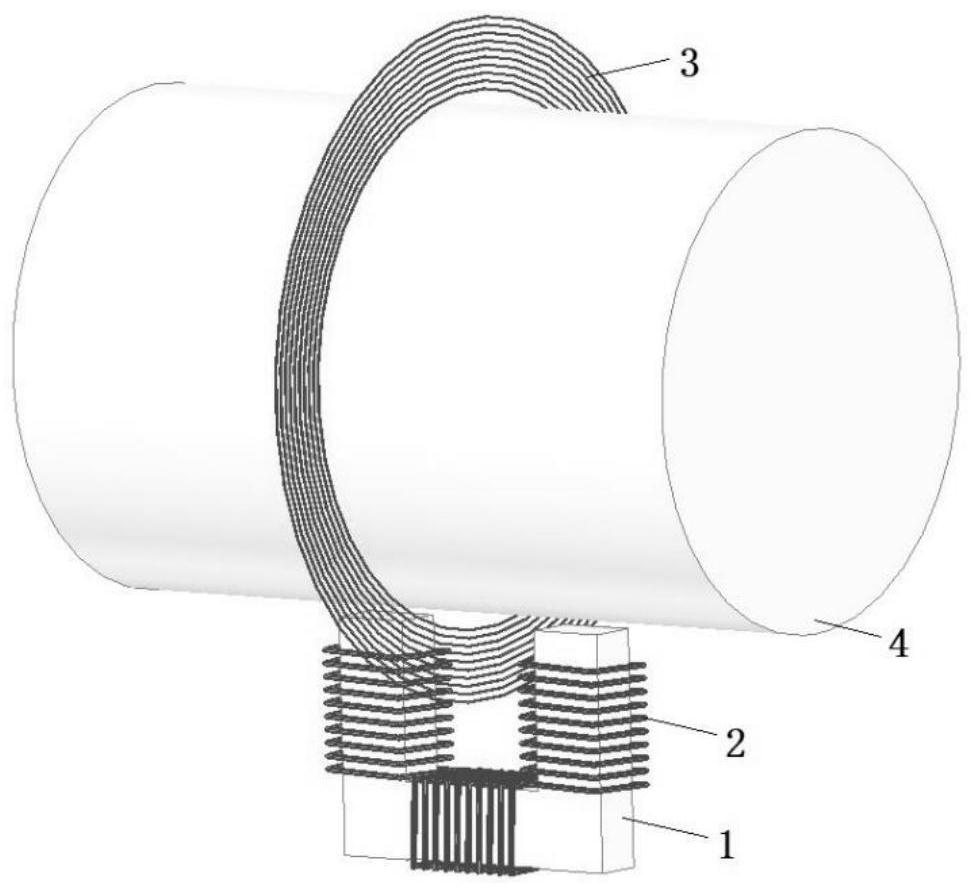
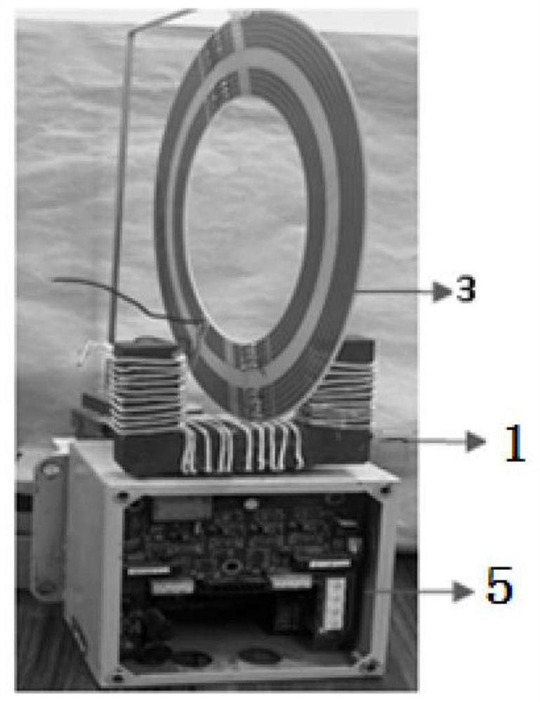
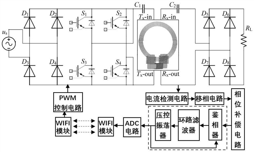
The invention provides a rolling mill torque on-line telemetering system based on a U-shaped electromagnetic coupling structure, relates to the technical field of torque measurement, and can realize long-term on-line monitoring of shaft torque parameters and ensure that a wireless power transmission system works in a resonance state. The system comprises an electromagnetic coupling structure, a primary side high-frequency inverter power supply circuit, a secondary side working circuit and a frequency tracking control circuit; the frequency tracking control circuit is used for sampling the current of the secondary side working circuit, carrying out frequency tracking, and carrying out frequency control over the primary side high-frequency inverter power supply circuit according to frequencytracking information; and the electromagnetic coupling structure comprises a primary side U-shaped magnetic core, a primary side coil wound on the magnetic core and a secondary side coil wound on theperiphery of a rotating shaft, and the edge of the secondary side coil is arranged in the primary side U-shaped magnetic core and located in the center. The technical scheme provided by the inventionis suitable for a rotating shaft torque measurement process.

Description

【Technical field】 [0001] The invention relates to the technical field of torque measurement, in particular to an on-line telemetry system for rolling mill torque based on a U-shaped electromagnetic coupling structure. 【Background technique】 [0002] The failure of the main drive electromechanical system of the rolling mill will affect the production plan, reduce the production efficiency, and bring huge economic losses to the iron and steel enterprises. The real-time online monitoring of equipment status can provide reliable and useful data information for the production process to ensure the safe and efficient operation of the equipment. The main drive torque of the rolling mill is one of the important force and energy parameters of the rolling mill during the rolling process. It not only reflects the main drive system The magnitude of the load it bears also reflects the dynamic process of torque changes. Therefore, online real-time monitoring of torque signals can optimiz...

Claims


Application Information

Patent Timeline
IPC IPC(8): B21B38/00
CPCB21B38/00
Inventor 贾金亮闫晓强闫雄孙运强
Owner UNIV OF SCI & TECH BEIJING
Learn More