Tool for solving problem that movable material of steel casting die is difficult to strip

A technology for steel castings and moulds, which is applied in the field of tools for solving the problems of steel casting mold live materials that are difficult to mold, and can solve the problems of reducing the yield of steel castings, low practicability, and mold deformation, so as to improve practicability and Effects of adaptability, increased flexibility and adaptability, increased stability and practicality

Inactive Publication Date: 2021-02-09
京山翼龙铸钢有限公司
7 Cites 1 Cited by

AI-Extracted Technical Summary

Problems solved by technology

[0006] In order to solve the above-mentioned technical problems, the present invention provides a tool for solving the difficulty in removing molds for steel casting mold live materials, to solve the problem that the existing circular steel castings are difficult to separate from the mold after cooling and forming in the mold, and usually require Only by...

Method used

Wherein, linkage clamping block 6 is the right-angled triangle design of inversion, and linkage clamping block 6 is plugged in the inner bottom of positioning track block 501, and the inside of linkage clamping block 6 and positioning track block 501 is provided with spring slot, and spring inserts The inside of the slot is provided with a fixed top spring 5011, and the two ends of the fixed top spring 5011 are fixedly connected to the inside of the spring slot of the linkage block 6 and the positioning track block 501 respectively. The linkage block 6 clamps the track stopper 401, drives the mold bottom shell 4 up and down, as shown in Figure 7, thereby completing the ejection operation of the formed steel casting, and the fixed top spring 5011 makes the linkage block 6 stable Clamping the track stopper 401 will prevent the linkage clamping block 6 from slipping off the track stopper 401, which will cause the failure of the function of device ejection and adjustment of the height of the mold bottom shell 4, which improves the stability of the device.
Wherein, mold bottom shell 4 is annula...

Abstract

The invention discloses a tool for solving the problem that a movable material of a steel casting die is difficult to strip, and relates to the technical field of stripping tools. The problems that when an annular steel casting in the prior art is stripped, the die is prone to being damaged, the steel casting is prone to being damaged by knocking, and the yield of steel casting production is reduced are solved. The tool for solving the problem that the movable material of the steel casting die is difficult to strip comprises a die bottom shell, and the die bottom shell is inserted into a die outer shell. When the device is used for stripping the steel casting, only a linkage rod needs to be lifted or rotated through a cross rod, the linkage rod can drive the die bottom shell to ascend through a linkage clamping block at the bottom of a track disc, so that the steel casting is separated from the die outer shell and a die inner shell for demolding, the die outer shell and the die inner shell are protected against damage, the stripped steel casting is complete and cannot be damaged by knocking, and the use is convenient; and when the linkage rod is rotated, the height of the die bottom shell can be changed, so that casting manufacturing of steel castings with different thicknesses is realized.

Application Domain

Foundry mouldsFoundry cores +2

Technology Topic

PhysicsEngineering +3

Image

  • Tool for solving problem that movable material of steel casting die is difficult to strip
  • Tool for solving problem that movable material of steel casting die is difficult to strip
  • Tool for solving problem that movable material of steel casting die is difficult to strip

Examples

  • Experimental program(1)

Example Embodiment

[0034] Example:
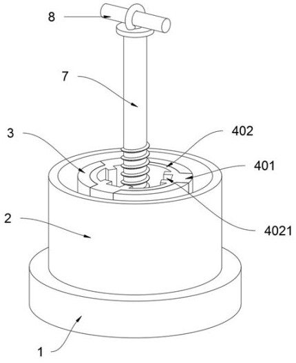
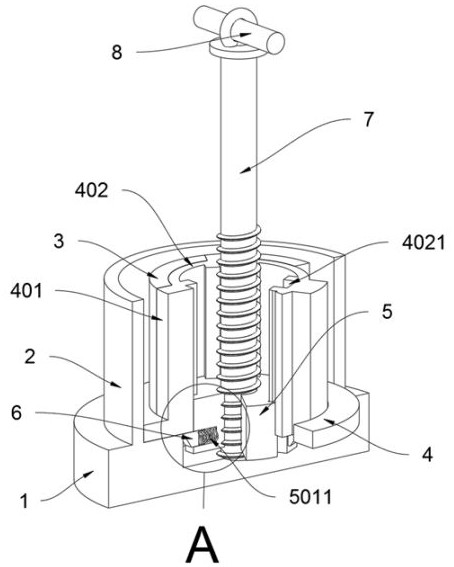
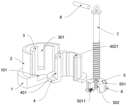
[0035] as attached figure 1 to attach Figure 8 Shown:
[0036]The present invention provides a tool for solving the difficulty in mold removal of steel casting mold live materials, including a mold base 1, a mold inner shell 3, a mold bottom shell 4, a track plate 5, a linkage block 6, a linkage rod 7 and a cross bar 8. The top of the mold base 1 is fixedly connected with the mold shell 2; the top surface of the mold base 1 is provided with an avoidance groove 101, and the inner diameter of the avoidance groove 101 is smaller than the outer diameter of the mold inner shell 3. This design makes the device There will be no material leakage when steel parts are used; the mold inner shell 3 is fixedly connected to the top surface of the mold base 1, and the mold inner shell 3 is located inside the mold shell 2; the mold bottom shell 4 is plugged into the mold shell 2; The top surface of the mold bottom shell 4 is provided with a track stopper 401, and there are three track stoppers 401, and the track stoppers 401 are evenly distributed on the side of the mold bottom shell 4 inner ring, and the shell of the mold inner shell 3 is provided with three lifts. The pull groove 301, and the track stopper 401 is plugged inside the pulling groove 301, this design enables the track stopper 401 to be plugged into the inside of the mold inner shell 3; the track disc 5 is plugged into the inside of the mold inner shell 3; The linkage block 6 is plugged into the bottom of the side of the orbital disc 5; the linkage rod 7 is inserted into the top surface of the orbital disc 5; The linkage rod 7 is screwed into the threaded hole 502 of the orbital disc 5. This design makes it possible for the linkage rod 7 to drive the orbital disc 5 up and down when the linkage rod 7 is rotated or pulled; within the ring.
[0037] Wherein, the mold bottom shell 4 is a ring-shaped design, and the outer diameter of the mold bottom shell 4 is the same as the inner diameter of the mold shell 2, and the inner diameter of the mold bottom shell 4 is the same as the outer diameter of the mold inner shell 3. This design makes the mold bottom shell 4. The bottom of the mold outer shell 2 and the mold inner shell 3 can be blocked. When the steel castings are poured, the device will not leak material, and the corresponding steel castings can be poured completely, which improves the performance of the device. Practicality and adaptability.
[0038] Wherein, the inside of the mold bottom shell 4 is provided with a shaped top ring 402, and the outer diameter of the shaped top ring 402 is the same as the inner diameter of the mold inner shell 3, and the outer side of the shaped top ring 402 is fixedly connected to the inner side of the track stopper 401, This design enables the shaped top ring 402 to support the inner shell 3 of the mold, so that the inner shell 3 of the mold will not collapse during the pouring process, which ensures the quality of steel castings and improves the quality of steel castings produced by the device Rate.
[0039] Wherein, the inside of the shaped top ring 402 is provided with a positioning groove 4021, and three positioning grooves 4021 are provided, and the side of the track disk 5 is provided with three positioning track blocks 501, and the positioning track blocks 501 are inserted in the inside of the positioning groove 4021, and the positioning The position of the groove 4021 inside the shaped top ring 402 is the same as the position of the outer rail stopper 401 of the shaped top ring 402. This design makes the positioning track block 501 plugged into the positioning groove 4021 so that the linkage block 6 is always at the track stopper The bottom of the 401 can block the bottom of the track stopper 401 to drive the mold bottom shell 4 up and down. The linkage block 6 is located inside the lifting groove 301 and will not be hindered by the mold inner shell 3 when it is lifted, and the mold bottom can be adjusted stably. Shell 4 height and function of ejection, as attached Figure 7 As shown, the stability and practicality of the device are improved.
[0040] Wherein, the linkage block 6 is an inverted right-angled triangle design, and the linkage block 6 is plugged into the inner bottom of the positioning track block 501. The inside of the linkage block 6 and the positioning track block 501 is provided with a spring slot, and the inside of the spring slot There is a fixed top spring 5011, and the two ends of the fixed top spring 5011 are fixedly connected to the inside of the spring slot of the linkage block 6 and the positioning track block 501 respectively. 6 Block the track stopper 401 to drive the mold bottom shell 4 up and down, as attached Figure 7 As shown, the ejection operation of the formed steel casting is completed, and the top spring 5011 is fixed so that the linkage block 6 can stably clamp the track stopper 401, and the linkage block 6 will not slip off the track stopper 401 to cause the device to start. The phenomenon that the mold and the function of adjusting the height of the mold bottom shell 4 fails occurs, which improves the stability of the device.
[0041] The specific usage and function of this embodiment:
[0042] In the present invention, the height of the mold bottom shell 4 inside the mold shell 2 and the mold inner shell 3 is adjusted according to the thickness of the manufactured steel casting, and the linkage lever 7 is rotated. When the linkage lever 7 is rotated, the linkage lever 7 can pass through the track disk 5 The threaded hole 502 on the top drives the track plate 5 up and down, and the track plate 5 lifts up and down. The linkage block 6 on the side of the track plate 5 blocks the track stopper 401, thereby driving the mold bottom shell 4 up and down, thereby completing the pouring thickness of the formed steel casting. adjustment, as attached Figure 7 As shown, after the adjustment is completed, it is sufficient to pour steel castings into the mold. The mold bottom shell 4 can seal the bottom of the mold shell 2 and the mold inner shell 3, and the device will not leak when the steel castings are pouring. The corresponding steel castings can be poured completely, and the shaped top ring 402 can support the mold inner shell 3, so that the mold inner shell 3 will not collapse during the pouring process, ensuring the production of steel castings Quality, when the steel casting needs to be removed after cooling and forming, it is only necessary to rotate or pull the linkage rod 7. When the linkage rod 7 is rotated or pulled, the linkage rod 7 can drive the orbital plate 5 up and down, and the orbital plate 5 can be lifted up and down. The linkage block 6 on the side of the track disc 5 blocks the track stopper 401, and drives the mold bottom shell 4 to lift. Figure 7 As shown, the ejection operation of the formed steel casting is completed, and the top spring 5011 is fixed so that the linkage block 6 can stably clamp the track stopper 401, and the linkage block 6 will not slip off the track stopper 401 to cause the device to start. The mold and the function of adjusting the height of the bottom shell 4 of the mold are invalid. The positioning track block 501 is plugged into the inside of the positioning groove 4021 so that the linkage block 6 is always at the bottom of the track stopper 401 so that the bottom of the track stopper 401 can be stuck Drive the mold bottom shell 4 up and down, the linkage block 6 is located inside the lifting groove 301 and will not be hindered by the mold inner shell 3 when lifting, and can stably realize the functions of adjusting the height of the mold bottom shell 4 and ejecting the mold, and the steel casting After the mold shell 2 and the mold inner shell 3 are taken out, the demoulding of the steel casting is completed, and the next process can be carried out after the steel casting is taken off, and the mold bottom shell 4 is reinserted into the inside of the mold inner shell 3 and the above steps are repeated. Castings can continue to be poured.

PUM

no PUM

Description & Claims & Application Information

We can also present the details of the Description, Claims and Application information to help users get a comprehensive understanding of the technical details of the patent, such as background art, summary of invention, brief description of drawings, description of embodiments, and other original content. On the other hand, users can also determine the specific scope of protection of the technology through the list of claims; as well as understand the changes in the life cycle of the technology with the presentation of the patent timeline. Login to view more.

Similar technology patents

Disposable medical-examination light

ActiveUS20090097236A1good visualizationeasy to use
Owner:UTAH MEDICAL PRODS

Patient positioning support structure

ActiveUS20120198625A1easy to useinexpensive to make
Owner:WARSAW ORTHOPEDIC INC

Classification and recommendation of technical efficacy words

  • Improve usability and stability
  • easy to use

Method and device for enhancing reliability and availability of dual-computer clusters

ActiveCN105681074AAvoid Rack Power Down IssuesImprove usability and stability
Owner:TOYOU FEIJI ELECTRONICS

Adjustable device for lamp cap glue spraying and drying

InactiveCN107199162AImprove usability and stability
Owner:张雪燕

Business knowledge management based configuration management method

InactiveCN104200324AGuarantee normal operationImprove usability and stability
Owner:CHINA NAT SOFTWARE & SERVICE

Autonomous monitoring coordination method for Internet of Things gateway

PendingCN114205190AAvoid service exceptionsImprove usability and stability
Owner:CHINA THREE GORGES CORPORATION

Energy-gathering buffering device for improving tunnel smooth blasting effect and blasting method utilizing same

ActiveCN113008091Aavoid mixingImprove usability and stability
Owner:NANJING UNIV OF TECH +1

Laser assisted total joint arthroplasty

InactiveUS20090234360A1easy to use
Owner:ALEXANDER VLADIMIR

Enclosure for a portable hemodialysis system

ActiveUS20090114582A1easy to use
Owner:DEKA PROD LLP
Why Eureka
Try Eureka