Environment-friendly bag handle bonding machine

A technology for bonding machines and environmentally friendly bags, which is applied in bag making operations, container manufacturing machinery, paper/cardboard containers, etc., and can solve problems such as low efficiency and wasting time

Inactive Publication Date: 2021-02-09
赵世伟
View PDF0 Cites 0 Cited by
  • Summary
  • Abstract
  • Description
  • Claims
  • Application Information

AI Technical Summary

Problems solved by technology

The process of overcoming the manual operation can only produce one at a time. This kind of production method is very inefficient and wastes a lot of time.

Method used


Image

  • Environment-friendly bag handle bonding machine
  • Environment-friendly bag handle bonding machine
  • Environment-friendly bag handle bonding machine

Examples


Embodiment 1

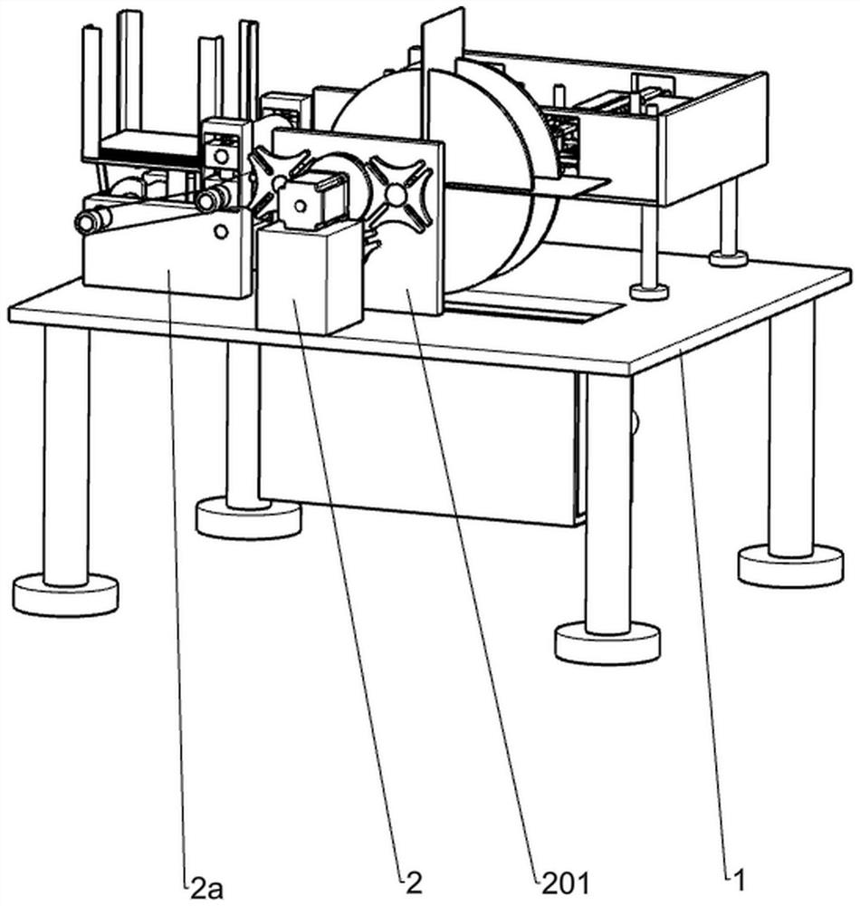
[0126] Such as Figure 1-Figure 15 As shown, an environmental protection bag handle bonding machine includes a frame 1, a power assembly, a feeding mechanism, a transmission mechanism, a turning mechanism, a glue dropping mechanism and a rope cutting mechanism, and the middle part of the frame 1 is provided with a rectangular large concave slot, the power assembly is set on one side of the frame 1, the feeding mechanism is fixedly installed on the upper left side of the frame 1, the power assembly is connected to the feeding mechanism, the transmission mechanism is installed on the upper left side of the frame 1, the transmission mechanism and the power The components are connected, the transmission mechanism is located on the right side of the feeding mechanism, the turning mechanism is installed in the upper middle of the frame 1, the turning mechanism is located above the groove opened in the frame, the turning mechanism is located on the right side of the transmission mecha...

Embodiment 2

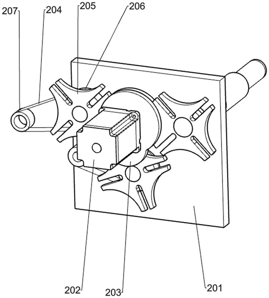
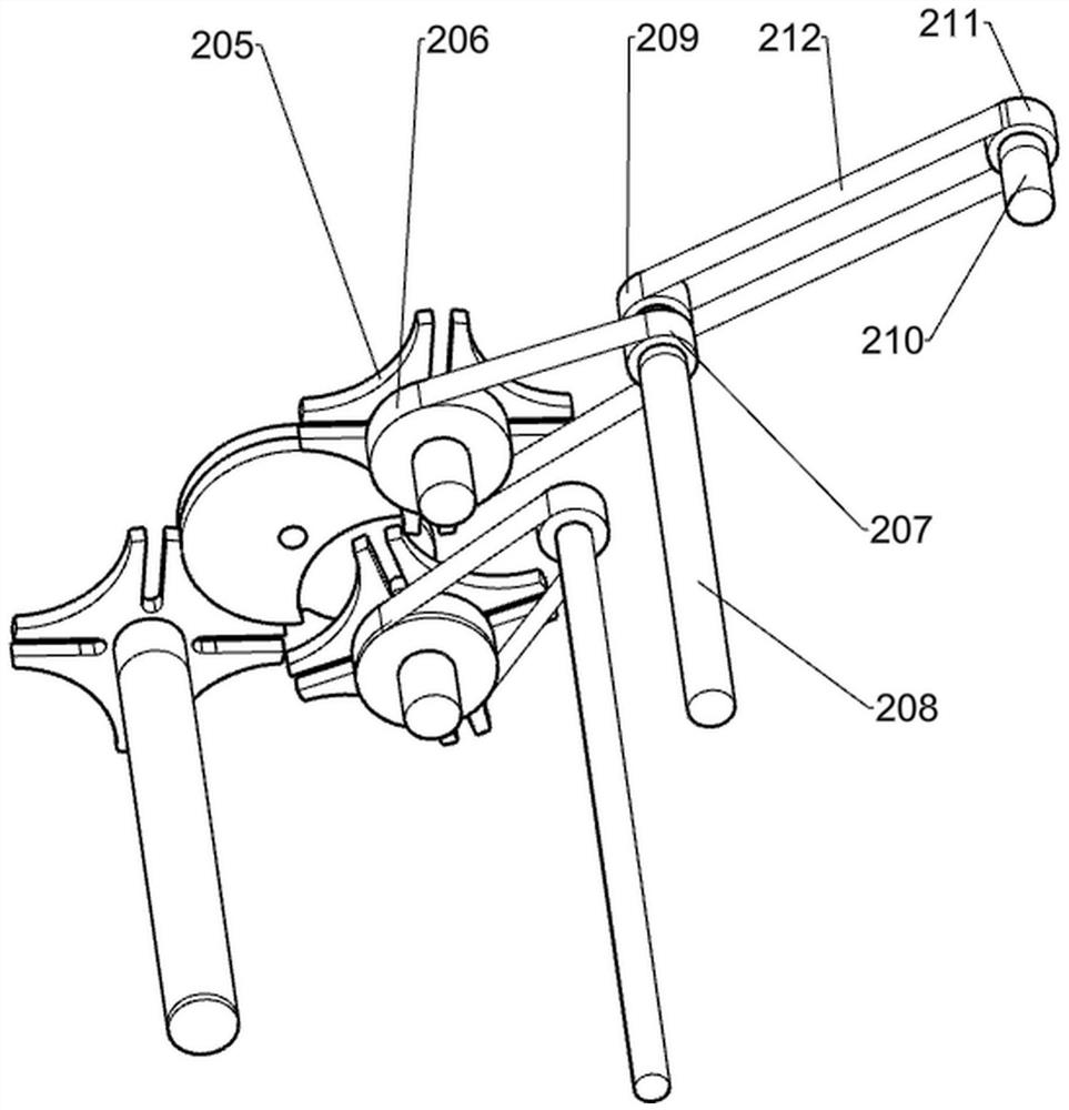
[0129] Such as Figure 3-Figure 6 As shown, based on Embodiment 1, the feeding mechanism includes a support table 2, a first support plate 2a, a second support plate 201, a motor 202, a dial 203, a first intermittent disc 205, a first pulley 206, First shaft 208, second shaft 208a, second pulley 207, first belt 204, third pulley 209, third shaft 210, fourth pulley 211, second belt 212, cam 213, set Material rack 214, slide rail 215, first slide plate 216, first slide block 2161, first spring 2162, pole 217, first roller 218 and first tension spring 219, support table 2 is fixedly installed on the top of frame 1 In the middle position of the front side, the two first support plates 2a are fixedly installed on the upper left front side of the frame 1, the two first support plates 2a are placed front and back, and the second support plate 201 is fixedly installed on the upper front side of the frame 1. The second support plate 201 is located at the rear side of the support platf...


PUM


Abstract

The invention relates to an environment-friendly bag handle bonding machine. The environment-friendly bag handle bonding machine comprises a rack, a feeding mechanism, a conveying mechanism, a turnover mechanism, a glue dripping mechanism and a rope cutting mechanism. A large rectangular groove is formed in the middle portion of the rack. The feeding mechanism is fixedly arranged on the left sideof the upper portion of the rack. The conveying mechanism is arranged on the left side of the upper portion of the rack. Two first supporting plates are arranged front and back, and a second supporting plate is fixedly arranged on the front side of the upper portion of the rack. Through additional arrangement of the glue dripping mechanism and the rope cutting mechanism, manual work is replaced with machines, and the glue dripping mechanism is driven by motor power to run so as to conduct glue dripping on the positions, needing rope bonding, of environment-friendly bags. The environment-friendly bag handle bonding machine is further provided with the turnover mechanism, after one faces of the environment-friendly bags are bonded, the turnover mechanism turns over the environment-friendly bags by 180 degrees, and bonding of the other faces of the environment-friendly bags is facilitated. After the turnover mechanism turns over the environment-friendly bags, the next environment-friendlybag bonding process can be conducted at the positions of the environment-friendly bags before the environment-friendly bags are turned over, the work efficiency is improved, and small-batch production is achieved.

Description

technical field [0001] The invention relates to a bonding machine, in particular to an environmental protection bag handle bonding machine. Background technique [0002] At present, the production process of portable environmental protection bags in the prior art is completed by a large-scale production line, which is not suitable for small batches. The production method of small batches of portable environmental protection bags is still manual. of bonding work. [0003] The operator prepares the environmental protection bag and the rope before bonding the environmental protection bag and the rope. During the bonding, the operator manually drops the glue on the environmental protection bag where the rope needs to be glued, and then manually presses the rope to the place where the glue is dripped. Position, press firmly until the glue cools and solidifies, after completing the bonding of one side, the bonding process of the other side is carried out, and the manual operation...

Claims


Application Information

Patent Timeline
Patent Type & Authority Applications(China)
IPC IPC(8): B31B70/86B31B70/62B31B70/04B31B70/74
CPCB31B70/04B31B70/62B31B70/74B31B70/864
Inventor 赵世伟
Owner 赵世伟
Why Eureka
Try Eureka