Carbon dioxide laser ink-jet printer

A carbon dioxide, inkjet printer technology, applied in typewriters, chemical instruments and methods, printing devices, etc., can solve the problems of inkjet quality impact, product damage, product displacement, etc., to facilitate clamping products, prevent damage, prevent The effect of output damage

Inactive Publication Date: 2021-02-09
陈志辉
View PDF0 Cites 1 Cited by
  • Summary
  • Abstract
  • Description
  • Claims
  • Application Information

AI Technical Summary

Problems solved by technology

[0003] The currently used carbon dioxide laser inkjet printers need to place the product to be coded on the workbench when in use, and have the inkjet dock to complete the focus and then perform the inkjet operation. In actual use, because the product is on the surface of the workbench The lack of a limit device can easily lead to the displacement of the product itself due to the influence of external force or the vibration of the device itself during the coding operation. At this time, it will lead to deviations in the coding position, which will easily affect the quality of the coding. If Using manual methods to assist product fixing, although it can solve the problem of coding deviation in a short time, but long-term use will still increase the workload of operators and affect work efficiency.
[0004] At the same time, in the existing device, after the laser inkjet printer completes the inkjet operation on the product, the coded product will directly drop from the outlet of the inkjet printer to the conveyor belt or platform, and there is a lack of control during the discharge process. The buffer device of the product, when the product falls from the discharge port to the platform or the conveyor belt, it is easy to cause damage to the product itself. It cannot provide certain protection for the product after the coding is completed, prevent the damage caused by the fall, and affect the final quality of the product.
[0005] At present, the laser inkjet printers used in the market produce a large amount of smoke on the surface of the workpiece due to high temperature during laser printing. When the smoke is not processed in time and is inhaled by the staff, it is easy to affect the health of the staff. For These fumes are not equipped with corresponding devices to deal with the fumes in the existing devices. Generally, the ventilation devices in the working space and the self-protection of the operators are used to realize the treatment of the fumes, but this treatment method is harmful to the toxic fumes. The treatment is limited and cannot meet the actual flue gas treatment needs

Method used


Image

  • Carbon dioxide laser ink-jet printer
  • Carbon dioxide laser ink-jet printer
  • Carbon dioxide laser ink-jet printer

Examples


Embodiment Construction

[0024] The following will clearly and completely describe the technical solutions in the embodiments of the present invention with reference to the accompanying drawings in the embodiments of the present invention. Obviously, the described embodiments are only some, not all, embodiments of the present invention. Based on the embodiments of the present invention, all other embodiments obtained by persons of ordinary skill in the art without making creative efforts belong to the protection scope of the present invention.

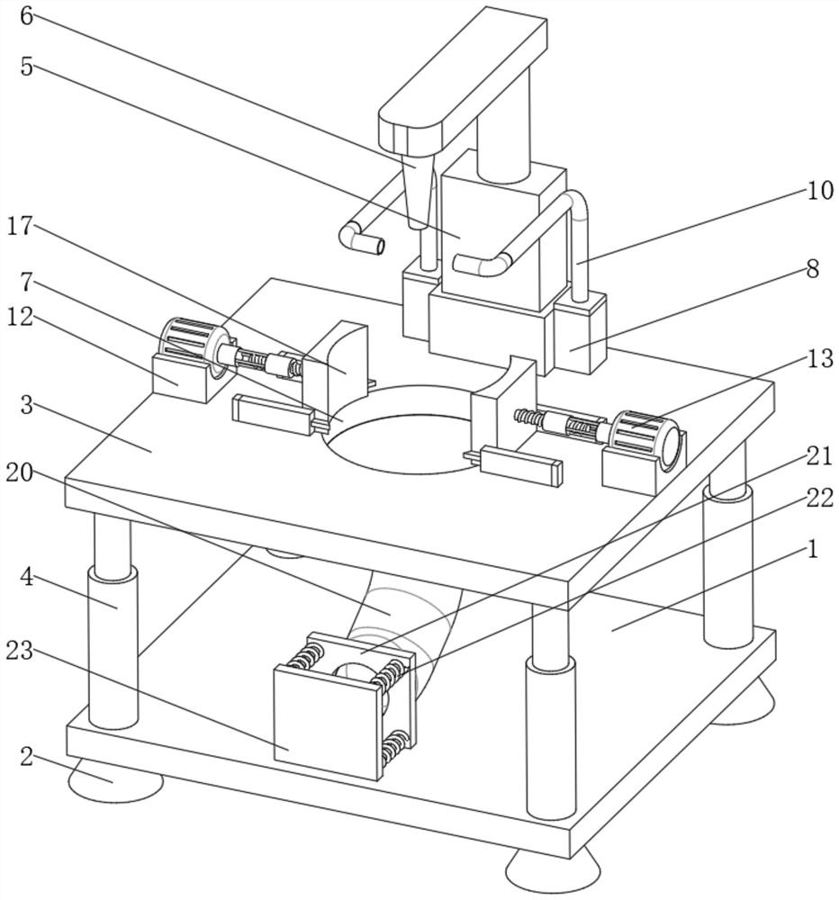
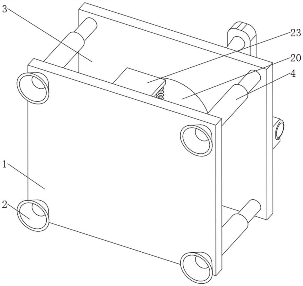
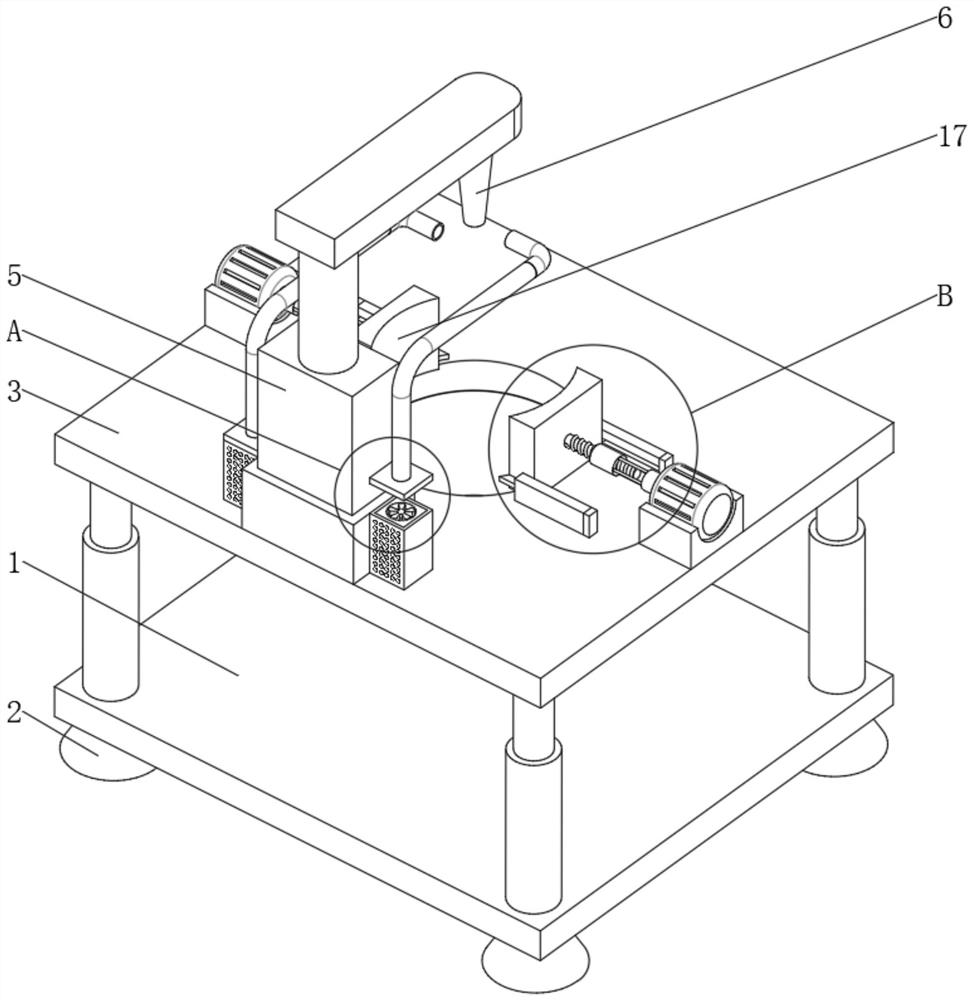
[0025] see Figure 1-5 , a carbon dioxide laser inkjet printer, comprising a bottom plate 1, a workbench 3 is provided on the top of the bottom plate 1, a through groove 7 is opened in the middle of the top of the workbench 3, and fixing seats 12 are fixedly installed on the left and right sides of the top of the workbench 3 , the top of the fixed base 12 is fixedly installed with a motor 13, one end of the output shaft of the motor 13 is fixedly installed wit...


PUM


Abstract

The invention relates to the technical field of laser ink-jet printing equipment, and discloses a carbon dioxide laser ink-jet printer. The carbon dioxide laser ink-jet printer comprises a bottom plate, wherein a workbench is arranged at the top end of the bottom plate, a through groove is formed in the middle of the top end of the workbench, fixing seats are fixedly installed on the left side andthe right side of the top end of the workbench, motors are fixedly installed at the top ends of the fixing seats, and connecting shafts are fixedly installed at one ends of output shafts of the motors at equal angles. According to the carbon dioxide laser ink-jet printer, the motors are started to drive the connecting shafts to move circumferentially and drive a threaded sleeve to rotate, at themoment, a threaded rod can be driven by the threaded sleeve to move relative to the threaded sleeve, two clamping plates can be driven by the threaded rod to get close to or get away from each other,sliding strips on the two sides of clamping plates can move in sliding rails to prevent the clamping plates from deviating, then clamping of a product to be subjected to ink-jet printing is completed,after ink-jet printing is completed, the clamping plates can be controlled to get away from each other to complete discharging, and therefore the advantage of conveniently clamping the product is achieved.

Description

technical field [0001] The invention relates to the technical field of laser coding equipment, in particular to a carbon dioxide laser coding machine. Background technique [0002] The inkjet printer is a device that is controlled by software and uses a non-contact method to mark on products. Generally refers to continuous inkjet technology (Continuous Inkjet Printer) referred to as CIJ. The inkjet printer theory was invented in the late 1960s, and the world's first commercial inkjet printer was not produced until the end of the 1970s. Among them, there is a laser inkjet printer classified according to the principle. The laser inkjet printer uses software to deflect the laser beam, and uses the high temperature of the laser to directly burn the surface of the product to be marked to form fonts or patterns. Laser inkjet printers mainly have the following advantages: reduce production costs, reduce consumables, and improve production efficiency; the anti-counterfeiting effec...

Claims


Application Information

Patent Timeline
Patent Type & Authority Applications(China)
IPC IPC(8): B41J2/435B41J3/01B41J29/00B01D53/00
CPCB01D53/00B41J2/435B41J3/01B41J29/00
Inventor 陈志辉
Owner 陈志辉
Why Eureka
Try Eureka