Flood drainage robot

A technology of a robot and a walking mechanism, applied in the field of emergency rescue and disaster relief equipment, can solve the problems of the overturning of the drainage robot, the heavy weight of the flood drainage robot, the inconvenience of setting up remote control electrical devices, etc., so as to achieve the effect of not easy to roll over.

Pending Publication Date: 2021-02-09
广州源创智能装备有限公司
View PDF0 Cites 4 Cited by
  • Summary
  • Abstract
  • Description
  • Claims
  • Application Information

AI Technical Summary

Problems solved by technology

[0002] Flood disasters often occur in large river basins and cities, and have the characteristics of uncertain time and place. When encountering a dangerous situation that requires large-scale rescue and disaster relief equipment to deal with, rescuers need to quickly transport the rescue and disaster relief equipment to the scene and put it into use. ; With the development of device intelligence technology, emergency rescue and disaster relief equipment is also developing towards automation and intelligence. The intelligent improvement of emergency rescue and disaster relief equipment enables it to be quickly put into emergency rescue and disaster relief work under the operation of rescuers. The robot installs the hydraulic system on the flood-discharging robot, which makes the flood-discharging robot relatively heavy, and the flood-discharging robot has a deep draft, making it inconvenient to install remote-controlled electrical devices for the flood-discharging robot; and the diesel engine in the hydraulic system is Vibration will be generated during the movement, which will easily cause the drainage robot to overturn when working in the water area, and because the flood drainage robot has a deep draft, it is not convenient for the diesel engine to inhale

Method used


Image

  • Flood drainage robot
  • Flood drainage robot
  • Flood drainage robot

Examples


Embodiment Construction

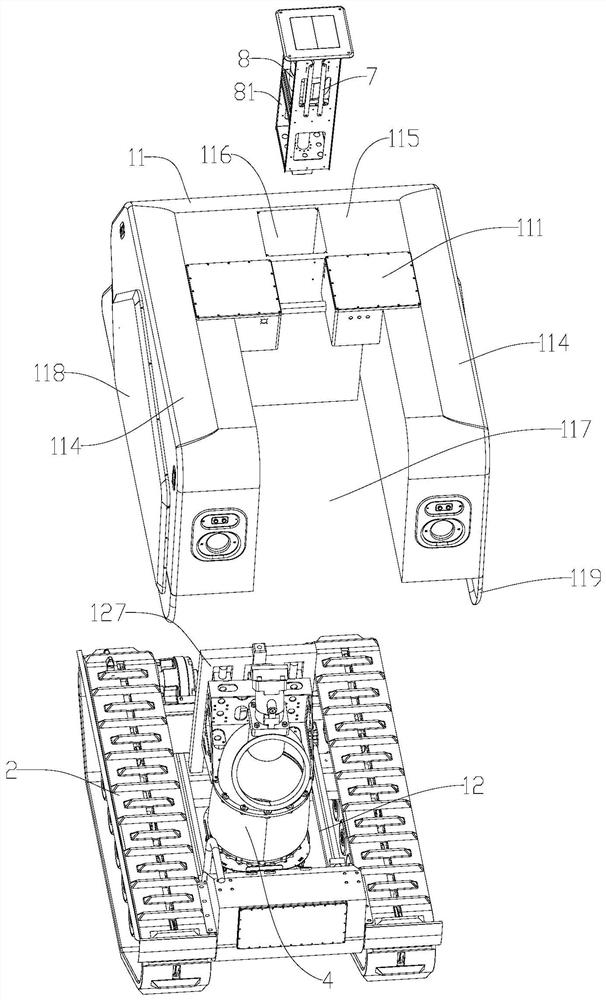
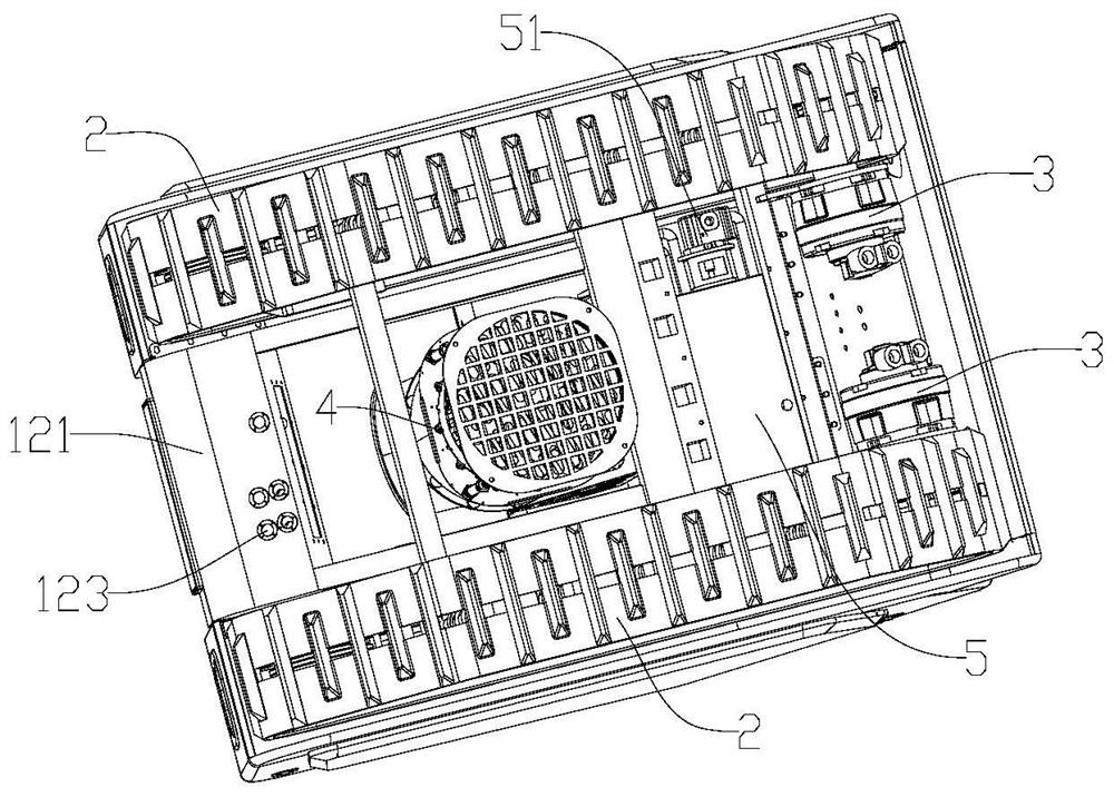
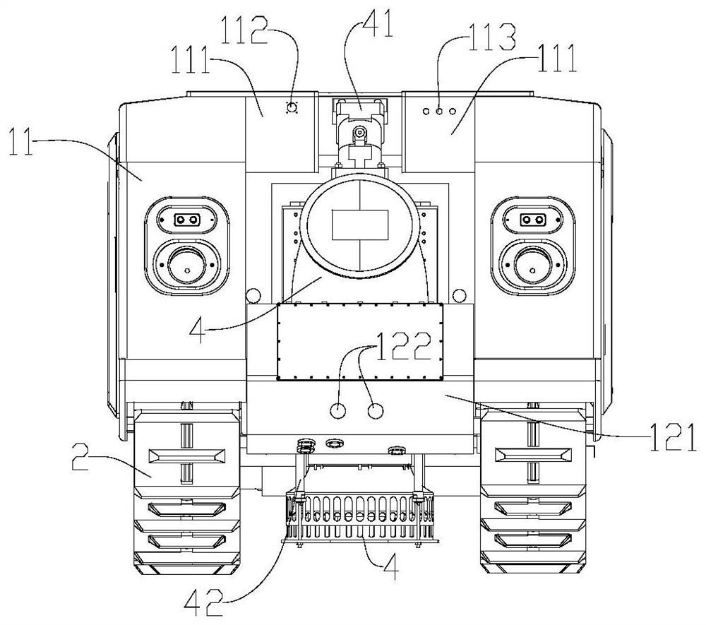
[0024] combined with Figures 1 to 8 Describe a kind of flood discharge robot of the present invention.

[0025] like Figure 1 to Figure 8 The flood discharge robot shown includes a main body 1 of the flood discharge robot, a hydraulic actuator, a water pump 4, a hydraulic pipeline, and a hydraulic power station. The hydraulic power station is placed outside the main body 1, and the hydraulic power The station is connected to the hydraulic pipeline on the main body 1 through the oil inlet pipe and the first oil return pipe, through which hydraulic power is provided for the hydraulic actuators on the main body 1, and the hydraulic pipeline includes the second oil return pipe and an overflow system, the second oil return pipe communicates with the first oil return pipe, and the overflow system is used to connect the overflow valve of the hydraulic actuator that needs to overflow to the second oil return pipe; the main body 1 includes Buoyancy cabin 11, base 12 and running gea...


PUM


Abstract

The invention relates to a flood drainage robot. The robot comprises a main body of the flood drainage robot, a hydraulic execution element, a water suction pump, a hydraulic pipeline and a hydraulicpower station, and the hydraulic power station is arranged outside the main body and connected with the hydraulic pipeline on the main body through an oil inlet pipe and a first oil return pipe. Hydraulic power is provided for the hydraulic execution element on the main body through the hydraulic pipeline, the hydraulic pipeline comprises a second oil return pipe and an overflow system, the secondoil return pipe is communicated with the first oil return pipe, and the overflow system allows an overflow valve of the hydraulic execution element needing to overflow to be connected into the secondoil return pipe; and the main body comprises a buoyancy cabin, a base and a walking mechanism, the base is arranged at the bottom of the buoyancy cabin, the walking mechanism is arranged on the base,an accommodating notch for at least allowing the water suction pump to be contained is formed in the buoyancy cabin, and the water suction pump is driven by the hydraulic execution element to performflood drainage operation. The invention aims to provide a structure of the flood drainage robot adopting the external hydraulic power station.

Description

technical field [0001] The invention relates to the field of rescue and disaster relief equipment, in particular to a flood discharge robot. Background technique [0002] Flood disasters often occur in large river basins and cities, and have the characteristics of uncertain time and place. When encountering a dangerous situation that requires large-scale rescue and disaster relief equipment to deal with, rescuers need to quickly transport the rescue and disaster relief equipment to the scene and put it into use. ; With the development of device intelligent technology, emergency rescue and disaster relief equipment is also developing towards automation and intelligence. The intelligent improvement of emergency rescue and disaster relief equipment enables it to be quickly put into emergency rescue and disaster relief work under the operation of rescuers. The robot sets the hydraulic system on the flood-discharging robot, which makes the flood-discharging robot relatively heavy...

Claims


Application Information

Patent Timeline
Patent Type & Authority Applications(China)
IPC IPC(8): F16M3/00F15B11/17F15B13/06F15B21/0423F04B9/10B60F3/00B62D55/06B62D11/00
CPCB60F3/00B62D11/00B62D55/06F04B9/10F15B11/17F15B13/06F15B2211/20576F15B2211/62F15B2211/78F16M3/00F15B21/0423
Inventor 田军朱财文
Owner 广州源创智能装备有限公司
Why Eureka
Try Eureka