Power amplitude limiter based on atmospheric pressure plasma and microwave discharge and test system

A plasma and microwave discharge technology, applied in instruments, measuring electricity, measuring devices, etc., can solve the problems of power limiter without detection system, slow power response speed, low power tolerance, etc., to solve the problem of slow power response speed , Faster response speed, effective measurement effect

Active Publication Date: 2021-02-09
SHANDONG NORMAL UNIV
View PDF9 Cites 0 Cited by
  • Summary
  • Abstract
  • Description
  • Claims
  • Application Information

AI Technical Summary

Problems solved by technology

The inventor found that traditional power limiters have disadvantages such as slow power response speed, low power tolerance, and narrow protection frequency band.
And there is no effective detection system for the power limiter, which can accurately judge the function test of the power limiter

Method used


Image

  • Power amplitude limiter based on atmospheric pressure plasma and microwave discharge and test system
  • Power amplitude limiter based on atmospheric pressure plasma and microwave discharge and test system
  • Power amplitude limiter based on atmospheric pressure plasma and microwave discharge and test system

Examples


Embodiment 1

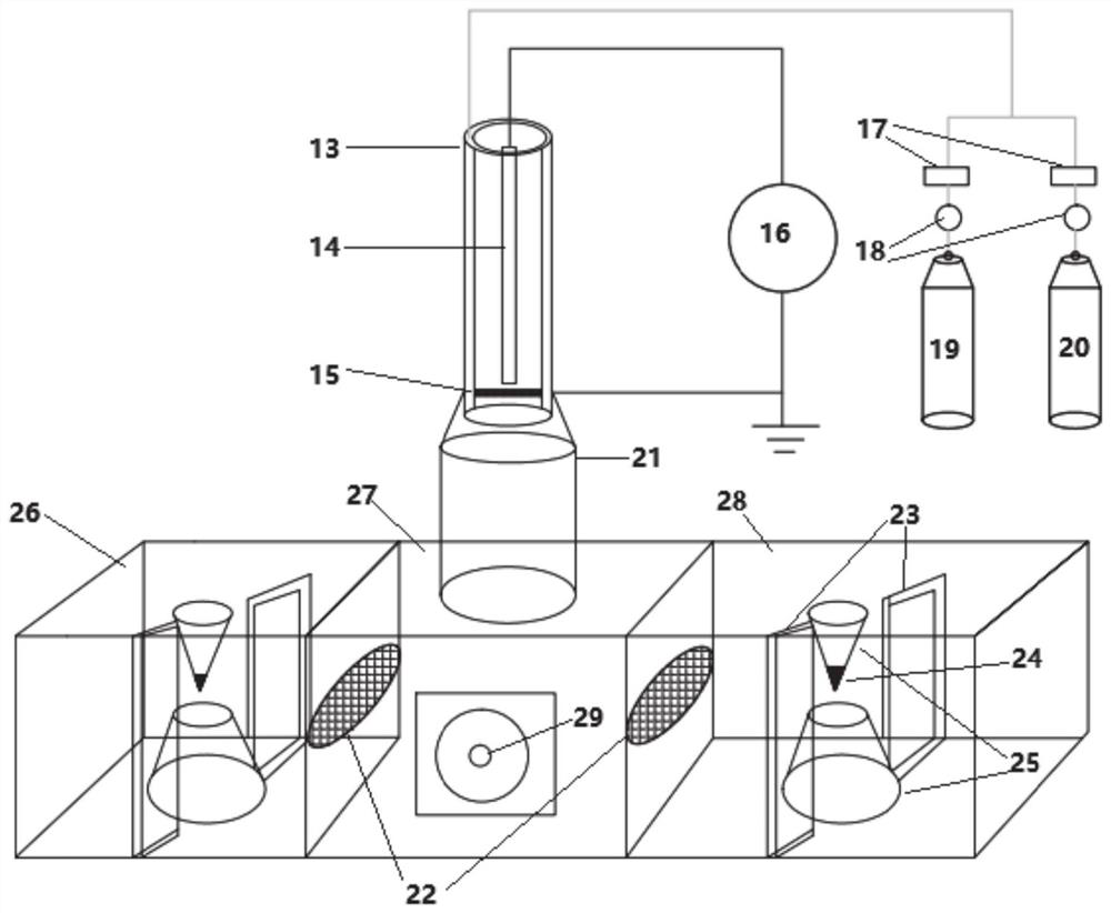
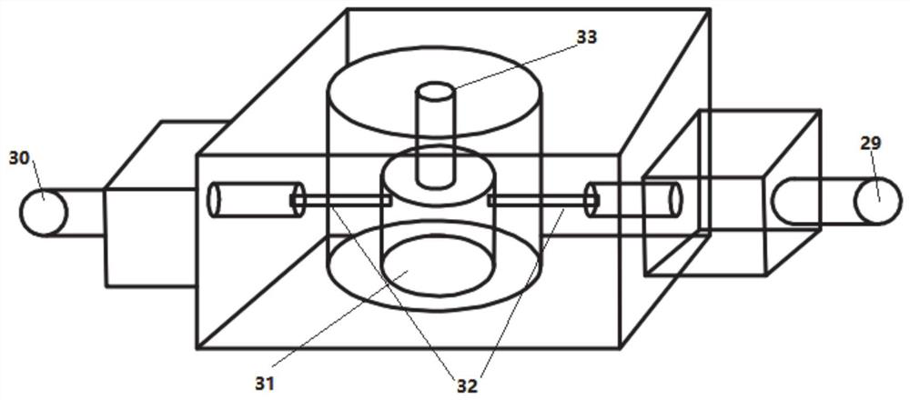
[0022] In the technical solutions disclosed in one or more embodiments, such as Figure 2-3 As shown, the power limiter based on atmospheric pressure plasma and microwave discharge includes an atmospheric pressure plasma jet generation device, a microwave power input device and a resonance device, and the atmospheric pressure plasma jet generation device and microwave power transmission device are respectively connected to the resonance device The discharge plasma generated by the atmospheric pressure plasma jet generating device contacts and merges with the discharge plasma generated by the microwave discharge of the incident signal of the microwave power transmission device, and reflects and attenuates the incident signal of the microwave power transmission device in the resonance device and outputs it.

[0023] In this embodiment, by setting the atmospheric pressure plasma jet generation device, the generated plasma jet can be incident on the resonance device, and the discha...

Embodiment 2

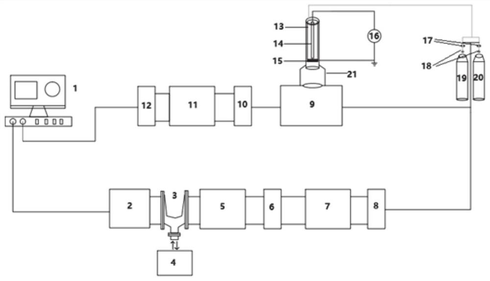
[0045] Based on embodiment 1, this embodiment provides the test system of the power limiter based on atmospheric pressure plasma and microwave discharge described in embodiment 1, such as figure 1 As shown, it includes a microwave signal supply circuit connected in sequence, the power limiter described in Embodiment 1, an output protection circuit and a signal detection device, and the microwave signal supply circuit is connected to the microwave of the power limiter described in Embodiment 1. The signal input terminal 29 and the output protection circuit are connected to the microwave signal output terminal 30 of the power limiter described in Embodiment 1.

[0046] In some embodiments, the microwave signal supply circuit includes a microwave signal generator 2, a power amplifier 5, an isolator 6, and a high-power directional coupler 7 connected in sequence, and the high-power directional coupler 7 is connected to the first SMA connector 8, and the The microwave signal is sen...


PUM


Abstract

The invention provides a microwave circuit power amplitude limiter based on atmospheric pressure discharge plasma and a test system, the power amplitude limiter comprises an atmospheric pressure plasma jet generation device, a microwave power input device and a resonance device, and the atmospheric pressure plasma jet generation device and the microwave power transmission device are respectively connected to a resonance device. Discharge plasmas generated by the atmospheric pressure plasma jet generation device are contacted and fused with discharge plasmas generated by microwave discharge ofincident signals of the microwave power transmission device, and the incident signals of the microwave power transmission device are reflected and attenuated in the resonance device and outputted. Atmospheric pressure discharge plasma is generated under the combined action of atmospheric pressure plasma jet and microwave discharge, the amplitude limiter can reflect and attenuate incident power ina microwave circuit, and has the advantages of being high in response speed, high in power tolerance, wide in protection frequency band and the like. The actual requirements of power amplitude limiting of high-power and high-frequency microwave circuits can be met.

Description

technical field [0001] The present disclosure relates to the technical field related to the limiter, in particular to a power limiter and a test system based on atmospheric pressure plasma and microwave discharge. Background technique [0002] The statements in this section merely provide background information related to the present disclosure and may not necessarily constitute prior art. [0003] In high-power and ultra-high-power radio frequency systems, the input terminal of the receiver is mainly protected by a limiter. The limiter is usually a pair of diodes connected in antiparallel between the signal input terminal and the ground. When the input is a small signal lower than the conduction voltage of the diode, the diode will not conduct, just like an open circuit, and will not affect the receiver. Work, when the input is a large signal higher than the diode conduction voltage, about 0.7V, the signal amplitude input to the receiver will be limited below the diode con...

Claims


Application Information

Patent Timeline
Patent Type & Authority Applications(China)
IPC IPC(8): G01R31/00
CPCG01R31/00
Inventor 潘杰刘鹏李英杰张雨璐宰程敏
Owner SHANDONG NORMAL UNIV
Why Eureka
Try Eureka