A six-layer wiring LCP package substrate, manufacturing method and multi-chip system-in-package structure
A technology for packaging substrates and substrates, which is applied in semiconductor/solid-state device manufacturing, semiconductor/solid-state device components, semiconductor devices, etc., to achieve high assembly efficiency, low moisture absorption and water permeability, oxygen transmission rate, and excellent high-frequency transmission characteristics Effect
- Summary
- Abstract
- Description
- Claims
- Application Information
AI Technical Summary
Problems solved by technology
Method used
Image
Examples
Embodiment 1
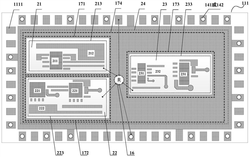
[0078] Such as figure 1 As shown, a six-layer wiring LCP packaging substrate of this embodiment includes:
[0079] 6 layers of patterned metal circuit layers distributed from the surface to the bottom surface, followed by the first layer of patterned metal circuit layer, the second layer of patterned metal circuit layer, the third layer of patterned metal circuit layer, and the fourth layer of patterned metal circuit layer layer, the fifth layer of patterned metal circuit layer, and the sixth layer of patterned metal circuit layer; on at least one side of the outermost edge of the first layer of patterned metal circuit layer, the external secondary cascading of the LCP packaging substrate is distributed Pads or graphics for I / O soldering;
[0080] 5 layers of insulating dielectric layers located between adjacent patterned metal circuit layers; each layer of the insulating dielectric layer is composed of an LCP substrate;
[0081] Located in the insulating dielectric layer be...
Embodiment 2
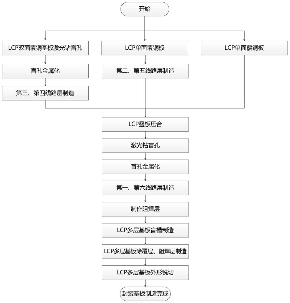
[0098] Such as image 3 As shown, this embodiment provides a method for manufacturing the six-layer wiring LCP packaging substrate 1 as described in Embodiment 1, including the following steps:
[0099] S1, such as Figure 4a As shown, blind holes are laser drilled on the double-sided copper-clad LCP substrate 153 to form third-type blind holes 143 that penetrate and connect the third patterned metal circuit layer 113 and the fourth layer patterned metal circuit layer 114. The blind holes Depth-to-diameter ratio≤1;
[0100] S2, such as Figure 4b As shown, the metallization of blind holes forms the third type of blind holes 143 filled with solid electroplated copper; The electroplating copper process is realized. After hole filling electroplating, the copper plating layer on the surface is thinned to form a third type of blind hole 143 filled with solid electroplated copper;
[0101] S3, such as Figure 4c As shown, the third layer of patterned metal circuit layer 113 and...
Embodiment 3
[0112] Such as Figure 5 As shown, based on the LCP packaging substrate described in Embodiment 1-2, this embodiment provides a multi-chip system-in-package structure 2, including: the LCP packaging substrate 1 as described in Embodiment 1-2, and chips 3, Metal enclosure 5 and metal cover plate 6;
[0113] The multi-chip system-in-package structure 2 is fixed on the PCB mother board by means of conductive adhesive bonding or welding, and the pads or patterns 1111 for external secondary cascading I / O welding on the LCP packaging substrate 1 are used. As the external secondary cascade I / O interface of the multi-chip system-in-package structure 2;
[0114] Metal ribs 51 are distributed in the metal surrounding frame 5; the metal surrounding frame 5 and the metal ribs 51 are welded on the upper surface of the LCP package substrate 1 and make the external secondary cascaded I / O welding pads or The figure 1111 is outside the metal frame 5, and the metal cover plate 6 is welded on ...
PUM
 Abstract
Description
Claims
Application Information
 - R&D
- Intellectual Property
- Life Sciences
- Materials
- Tech Scout
- Unparalleled Data Quality
- Higher Quality Content
- 60% Fewer Hallucinations
Browse by: Latest US Patents, China's latest patents, Technical Efficacy Thesaurus, Application Domain, Technology Topic, Popular Technical Reports.
© 2025 PatSnap. All rights reserved.Legal|Privacy policy|Modern Slavery Act Transparency Statement|Sitemap|About US| Contact US: help@patsnap.com


