Novel mop with disinfection function
A self-contained mop technology, applied in the field of household sanitary appliances, can solve the problems of bacterial growth, unhygienic mopped ground, and self-cleaning, etc., and achieve the effect of enhancing the service life
- Summary
- Abstract
- Description
- Claims
- Application Information
AI Technical Summary
Problems solved by technology
Method used
Image

Examples
Embodiment 1
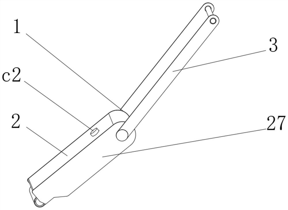
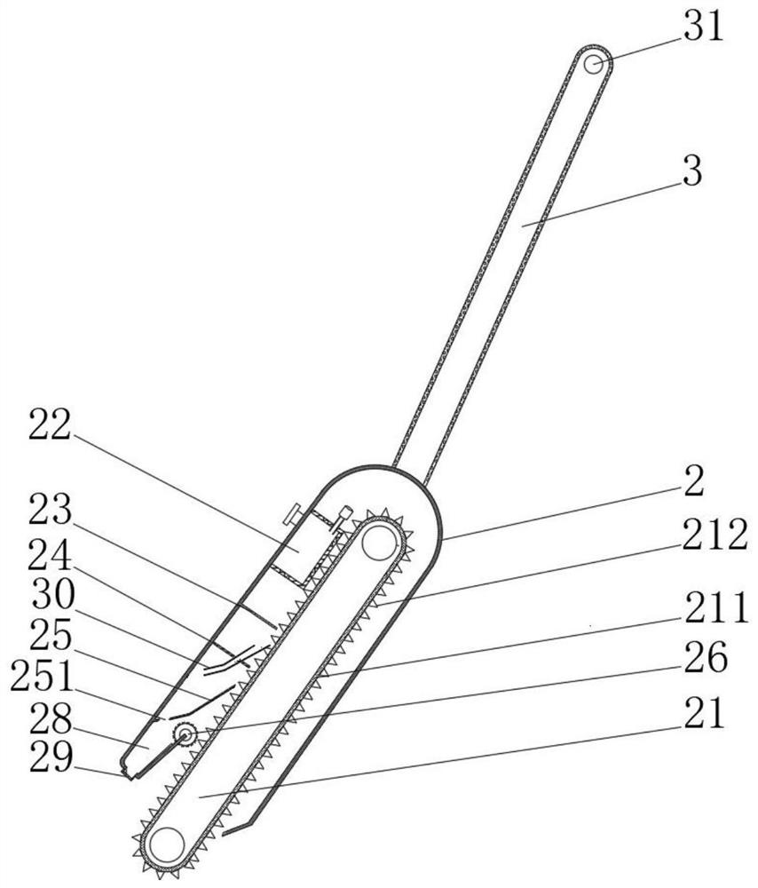
[0047] see Figure 1-2 , the present invention provides a technical solution: a new type of mop with disinfection function, comprising a mop body 1 composed of an outer shell 2 and a support rod 3, a conveying mechanism 21 is arranged inside the outer shell 2, and a disinfecting mop is arranged on the top of the conveying mechanism 21. device 22, the left side of the lower part of the sterilizer 22 is provided with an ash roller 23, a layered brush 24, a sliding ash plate 25 and a rolling mechanism 26 in sequence, and the two sides of the shell 2 are respectively fixedly connected with side plates 27, and the left side of the shell 2 A cavity 28 is formed, a valve 29 is arranged on the left side of the bottom of the casing 2, the left side of the sliding ash plate 25 is fixedly connected with the inside of the casing 2, and a through hole 251 is opened inside the ash sliding plate 25, and the conveying mechanism 21 includes a conveyor belt 211, the conveyor belt 211 is rotatio...
Embodiment 2
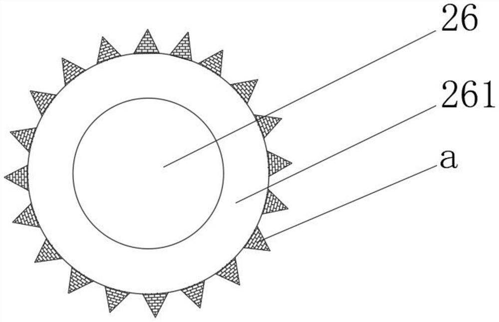
[0049] see Figure 1-4 On the basis of Embodiment 1, the present invention provides a technical solution: the rolling mechanism 26 includes a rolling rod 261, the rolling rod 261 is rotationally connected with the inside of the housing 2 through a bearing, and the circumferential side of the rolling rod 261 is fixedly connected with a rotating brush a , the rotating brush a includes a first receiving block a1, the bottom of the first receiving block a1 is fixedly connected with the circumferential side of the rolling rod 261, the first receiving block a1 is provided with a first magnet block a2, and the two sides of the first magnet block a2 The piston rod a3 is fixedly connected respectively, the top of the piston rod a3 is fixedly connected with the second receiving block a4, the outer wall of the second receiving block a4 is slidingly connected with the inner wall of the first receiving block a1, and the outer side of the second receiving block a4 is fixedly connected with ...
Embodiment 3
[0051] see Figure 1-7 , On the basis of Embodiment 1 and Embodiment 2, the present invention provides a technical solution: the layered brush 24 includes a first elastic strip 241, the top of the first elastic strip 241 is fixedly connected with a first elastic sheet 242, the first The bottom of the elastic strip 241 is fixedly connected with a first elastic block 243, the inside of the first elastic block 243 is provided with a first cavity film 244, the bottom of the first elastic block 243 is fixedly connected with an elastic brush 245, the first elastic piece 242 The top is fixedly connected with the inside of the shell 2, the ash roller 23 includes a second elastic strip 231, the top of the second elastic strip 231 is fixedly connected with a second elastic piece 232, and the bottom of the second elastic strip 231 is fixedly connected with a second elastic block 233, the inside of the second elastic block 233 is provided with a second cavity film 234, the bottom of the s...
PUM
 Abstract
Description
Claims
Application Information
 - R&D
- Intellectual Property
- Life Sciences
- Materials
- Tech Scout
- Unparalleled Data Quality
- Higher Quality Content
- 60% Fewer Hallucinations
Browse by: Latest US Patents, China's latest patents, Technical Efficacy Thesaurus, Application Domain, Technology Topic, Popular Technical Reports.
© 2025 PatSnap. All rights reserved.Legal|Privacy policy|Modern Slavery Act Transparency Statement|Sitemap|About US| Contact US: help@patsnap.com