
Crushing device for building construction and using method thereof

A crushing device and construction technology, applied in grain processing, electrode structure, electrostatic separation, etc., can solve the problems of sufficient crushing of stones, poor crushing effect, and affecting the effect of recycling

Pending Publication Date: 2021-02-12
魏雪
View PDF8 Cites 12 Cited by
  • Summary
  • Abstract
  • Description
  • Claims
  • Application Information

AI Technical Summary

Problems solved by technology

[0002] Building construction refers to the production activities in the implementation stage of engineering construction. It is the construction process of various buildings. It can also be said to be the process of turning various lines on the design drawings into physical objects at designated locations. It includes basic engineering construction. , main structure construction, roofing engineering construction, decoration engineering construction, etc. During the construction process, it is often necessary to use construction waste to fill some deep pits on the ground. Construction waste refers to slag blocks or concrete blocks from demolished buildings. Before these construction wastes, these slag blocks or concrete blocks will have large pieces, which need to be crushed before they can be used. However, the existing crushers cannot fully crush the stones only by grinding and squeezing between the crushing rollers. thus making the crushing effect poor
[0003] Furthermore, multiple times of manual crushing are required, which consumes manpower and material resources. At the same time, insufficient crushing of slag or concrete blocks will affect the effect of recycling.

Method used


Image

  • Crushing device for building construction and using method thereof
  • Crushing device for building construction and using method thereof
  • Crushing device for building construction and using method thereof

Examples


Embodiment 1

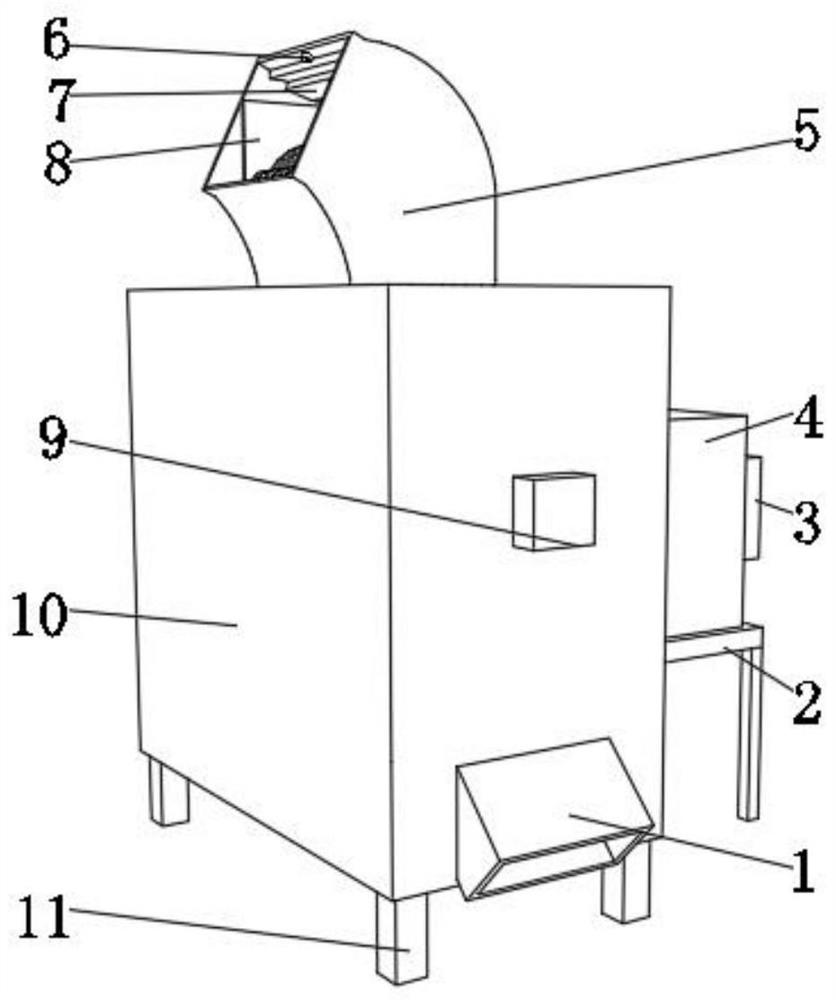
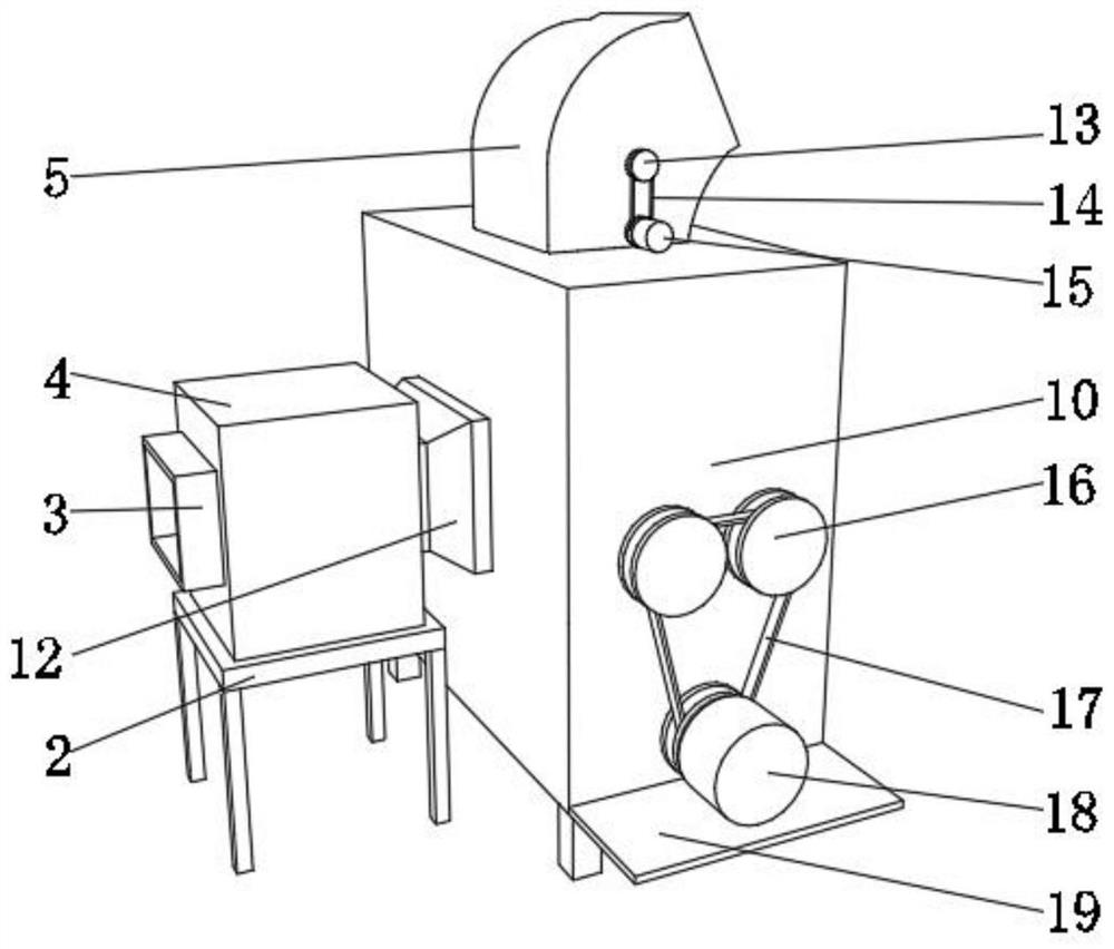
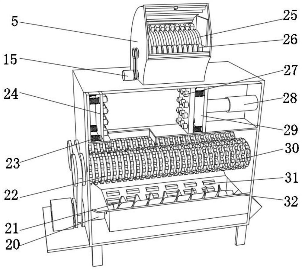
[0038] A crushing device for building construction, such as Figure 1-6 As shown, it includes a box body 10, the top of the box body 10 is fixed with a casing 5 by bolts, the outer wall of the opposite side of the casing 5 is fixed with a magnetic plate 8 by bolts, and the inner wall of the top side of the casing 5 is fixed with a metal plate by bolts. The sensor 6, the inner wall of the casing 5 is provided with a crushing mechanism, the bottom outer wall of the box body 10 is fixed with four support feet 11 by bolts, the outer wall of the bottom side of the box body 10 is fixed with a discharge pipe 1 by threads, and one part of the box body 10 The fan 9 is fixed on the outer wall of the side by bolts, the inner wall of one side of the box body 10 is fixed with a partition 33 by bolts, the outer wall of the top side of the partition 33 is provided with an extruding mechanism, and the outer wall of one side of the partition 33 is placed with a filter plate 34 One side outer w...

Embodiment 2

[0045] A crushing device for building construction, such as Figure 5 As shown, it includes a filter plate 34, the top outer wall of the filter plate 34 is fixed with more than three spikes 41 by bolts, the outer wall of the bottom side of the filter plate 34 is fixed with more than three springs 35 by bolts, and the other end of the spring two 35 There are two fixed plates 43 fixed by bolts, and two electric motors 42 are fixed on one side of the outer wall of one fixed plate 43 by bolts, and the output end of each electric motor 42 is fixed by a coupling so that one of the sides rotates. Axle two 37, one end of each rotating shaft two 37 is all fixed with rotating plate 38 by bolt, and the opposite side of every two rotating plates 38 is fixed with cam 36 by rotating shaft, and the top outer wall of each cam 36 is fixed with connection by rotating shaft. Rod 39, the top of connecting rod 39 is fixed with fixed block 40 by bolt, and the top outer wall of fixed block 40 is con...

Embodiment 3

[0048] A crushing device for building construction also uses a filter plate, such as Figure 5 As shown, it includes a dust collection box 4, the inner wall of the side of the dust collection box 4 near the connecting pipe 12 and the exhaust pipe 3 is fixed with an air flow distribution plate 46 by bolts, and the inner wall of the dust collecting box 4 is close to the side of the connecting pipe 12. The inner wall of one side is fixed with more than three anode plates 44 by bolts, the side of the dust collection box 4 close to the exhaust pipe 3 is fixed with more than three cathode plates 45 by bolts, and the bottom of the dust collection box 4 is fixed by bolts on the side close to the cathode plates 45 There is a rapping anvil 47, and the bottom of the dust collection box 4 is fixed with an ash discharge pipe through threads; when in use, the smoke and dust in the box body 10 enters the dust collection box 4 through the connecting pipe 12, and the smoke and dust gas is evenl...


PUM


Abstract

The invention discloses a crushing device for building construction and a using method thereof, and relates to the technical field of building construction. The problem of blockage in the crushing process is solved. The crushing device specifically comprises a box body, a shell is fixed to the top of the box body through bolts, a magnetic attraction plate is fixed to the outer wall of the oppositeside of the shell through bolts, a metal sensor is fixed to the inner wall of one side of the top of the shell through bolts, a crushing mechanism is arranged on the inner wall of the shell, four supporting legs are fixed to the outer wall of the bottom of the box body through bolts, a discharging pipe is fixed to the outer wall of one side of the bottom of the box body through threads, a fan isfixed to the outer wall of one side of the box body through bolts, a partition plate is fixed to the inner wall of one side of the box body through bolts, an extrusion mechanism is arranged on the outer wall of one side of the top of the partition plate, and a filter plate is placed on the outer wall of one side of the partition plate. According to the crushing device, an electric motor is started, so that the output end of the electric motor drives the filter plate and spines to reciprocate, and it is avoided that stones stay and accumulate on the filter plate and are crushed again at the same time.

Description

technical field [0001] The invention relates to the technical field of building construction, in particular to a crushing device for building construction and a method for using the same. Background technique [0002] Building construction refers to the production activities in the implementation stage of engineering construction. It is the construction process of various buildings. It can also be said to be the process of turning various lines on the design drawings into physical objects at designated locations. It includes basic engineering construction. , main structure construction, roofing engineering construction, decoration engineering construction, etc. During the construction process, it is often necessary to use construction waste to fill some deep pits on the ground. Construction waste refers to slag blocks or concrete blocks from demolished buildings. Before these construction wastes, these slag blocks or concrete blocks will have large pieces, which need to be c...

Claims


Application Information

Patent Timeline
Patent Type & Authority Applications(China)
IPC IPC(8): B02C13/02B02C1/00B02C4/08B02C18/14B02C21/00B02C23/16B02C23/00B03C3/41B03C3/47B03C3/76
CPCB02C1/005B02C4/08B02C13/02B02C18/0092B02C18/14B02C21/00B02C23/00B02C23/16B02C2023/165B02C2201/06B03C3/41B03C3/47B03C3/76
Inventor 魏雪
Owner 魏雪
Learn More