Embroidery machine for spinning and using method

A technology of machinery, textile cloth

Inactive Publication Date: 2021-02-12
王玉立
View PDF0 Cites 0 Cited by
  • Summary
  • Abstract
  • Description
  • Claims
  • Application Information

AI Technical Summary

Problems solved by technology

[0002] An embroidery machine for textiles, which drives the operation of the entire embroidery machine centrally through one servo machine, replacing the traditional multiple distributed small servo machines. It is easy to operate, effectively simplifies the complexity of the system, and improves work efficiency. The intelligent system on the right side of the embroidery machine controls the work. After the workers give the operation order, the machine can be completed accurately. It can not only control accurately, but also achieve the purpose of fast production speed. Through the new lifting mechanism, the lifting of the head is controlled centrally. The production efficiency of the embroidery machine weaving is greatly improved, but the embroidery frame for the existing textile embroidery machine is usually fixedly arranged under the embroidery machine, which makes it very inconvenient to place the embroidery cloth, and when the embroidery cloth is embroidered, It is only laid flat on the embroidery frame, which will easily cause the embroidery cloth to loosen, cause embroidery errors, or confusion, and it is complicated to adjust the height of the embroidery needles. Therefore, we propose an embroidery machine for textile use and its use method

Method used


Image

  • Embroidery machine for spinning and using method
  • Embroidery machine for spinning and using method
  • Embroidery machine for spinning and using method

Examples


Embodiment Construction

[0025] The following will clearly and completely describe the technical solutions in the embodiments of the present invention with reference to the accompanying drawings in the embodiments of the present invention. Obviously, the described embodiments are only some, not all, embodiments of the present invention. Based on the embodiments of the present invention, all other embodiments obtained by persons of ordinary skill in the art without making creative efforts belong to the protection scope of the present invention.

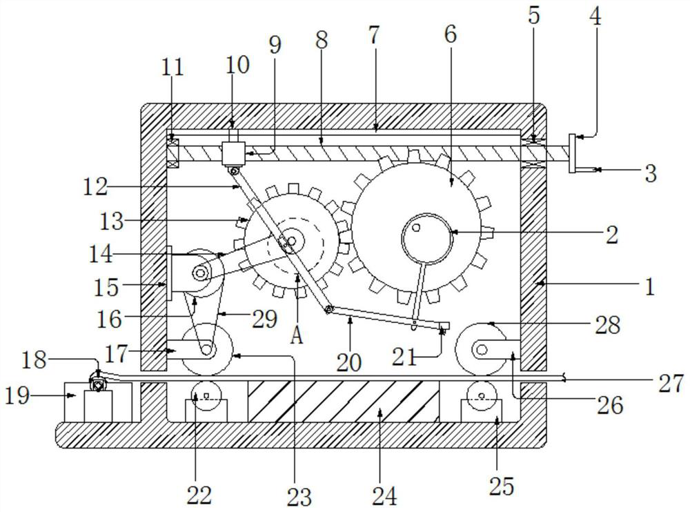
[0026] see figure 1 , the present invention provides a technical solution: an embroidery machine for weaving, comprising a housing 1, a chute 7 is provided on the top transverse central axis of the inner cavity of the housing 1, and a chute 7 is provided on the upper end of the longitudinal central axis of the left side of the inner cavity of the housing 1. There is a supporting bearing 11, the inner cavity of the supporting bearing 11 is equipped with a threa...


PUM

PropertyMeasurementUnit
Heightaaaaaaaaaa

Abstract

The invention discloses an embroidery machine for spinning and a using method in the technical field of textile equipment. The embroidery machine comprises a shell, wherein a sliding groove is formedin the transverse center axis of the top end of an inner cavity of the shell, a supporting bearing is arranged at the upper end of the longitudinal center axis of the left side face of the inner cavity of the shell, a threaded rod is installed in an inner cavity of the supporting bearing, the right end of the threaded rod penetrates through the upper portion of a right side panel of the shell to the right side of the shell, a rotating bearing is arranged on the upper portion of the central axis of the right side panel of the shell, the inner ring of the rotating bearing is connected with the threaded rod in a sleeving mode, a disc is arranged at the right end of the threaded rod, a rocker is arranged on the upper end face of the disc, a sleeve sleeves the left side of the outer portion ofthe threaded rod, a sliding block is arranged on the upper end face of the sleeve, the sliding block is arranged on the left side of an inner cavity of the slide groove, a driving motor is arranged inthe middle of a left side panel of the inner cavity of the shell, a belt wheel is arranged in the middle of a motor shaft of the driving motor, and a driving gear is movably connected to the front end face and the rear end face of the inner cavity of the shell. The embroidering machine is simple in structure and convenient to operate, the embroidering efficiency can be effectively improved, and the embroidering quality of textile fabrics can be improved.

Description

technical field [0001] The invention relates to the technical field of textile equipment, in particular to an embroidery machine for textile use and a method for using it. Background technique [0002] An embroidery machine for textiles, which drives the operation of the entire embroidery machine centrally through one servo machine, replacing the traditional multiple distributed small servo machines. It is easy to operate, effectively simplifies the complexity of the system, and improves work efficiency. The intelligent system on the right side of the embroidery machine controls the work. After the workers give the operation order, the machine can be completed accurately. It can not only control accurately, but also achieve the purpose of fast production speed. Through the new lifting mechanism, the lifting of the head is controlled centrally. The production efficiency of the embroidery machine weaving is greatly improved, but the embroidery frame for the existing textile em...

Claims


Application Information

Patent Timeline
IPC IPC(8): D05C11/06D05C9/06D05C9/20
CPCD05C9/06D05C9/20D05C11/06
Inventor 王玉立
Owner 王玉立
Why Eureka
Try Eureka