Hazardous waste rotary kiln incineration air supply method

A rotary kiln and air supply technology, applied in the combustion method, incinerator, combustion type, etc., can solve the problems of heat loss, increase in the rate of reduction on hot ignition of the moving speed, and high excess air coefficient of the rotary kiln, and achieve low The effect of increasing the burning rate

Pending Publication Date: 2021-02-12
XINZHONGTIAN ENVIRONMENTAL PROTECTION
View PDF6 Cites 0 Cited by
  • Summary
  • Abstract
  • Description
  • Claims
  • Application Information

AI Technical Summary

Problems solved by technology

[0003] Usually, if the air passing into the rotary kiln cannot be sufficiently diffused, the formed flow field is not fully covered, and the moving speed along the axis of the rotary kiln is too high, etc., the thermal loss rate will increase, that is, the full combustion of hazardous waste cannot be guaranteed. The method is to increase the air supply, but this will make the excess air coefficient of the rotary kiln too high, resulting in a large loss of heat. Ensure that the thermal loss rate is within the range of 5% to 8%, and the air excess coefficient of the rotary kiln has reached 1.5 to 2.0. Therefore, it is necessary to ensure both a low thermal loss rate and a low air excess coefficient at present. Hazardous waste incineration Key research topics of rotary kiln

Method used


Image

  • Hazardous waste rotary kiln incineration air supply method
  • Hazardous waste rotary kiln incineration air supply method
  • Hazardous waste rotary kiln incineration air supply method

Examples


Embodiment 1

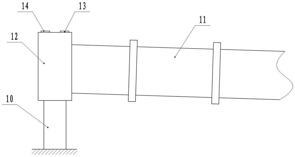
[0031] The air supply method for hazardous waste rotary kiln incineration is realized by using an improved air supply structure, in which the improved air supply structure is combined with figure 1 As shown, it includes a support frame 10, a drum 11 and a kiln head cover 12, wherein the drum 11 is rotatably connected to the support frame 10, and the kiln head cover 12 is fixed on the support frame 10. Between the drum 11 and the kiln head cover 12 In order to rotate and seal the connection, the drum 11 is arranged obliquely, and the end of the drum 11 near the kiln head cover 12 is higher than the other end.

[0032] The kiln head cover 12 includes a cylindrical outer wall and end covers connected to the two ends of the outer wall. The outer wall of the kiln head cover 12 is provided with a main air hole 13 and a secondary air hole 14, wherein the main air hole 13 is located at the top of the outer wall, and the main air hole 13 is located at the top of the outer wall. Both th...

Embodiment 2

[0036] The difference from Example 1 is that in this example, D=1.5d; through model simulation calculation, a conclusion similar to that of Example 1 is obtained, that is, the air excess coefficient of hazardous waste incineration is controlled between 0.8 and 1.0 to control the air The feed rate of hazardous waste incineration in the rotary kiln is less than 3%.

Embodiment 3

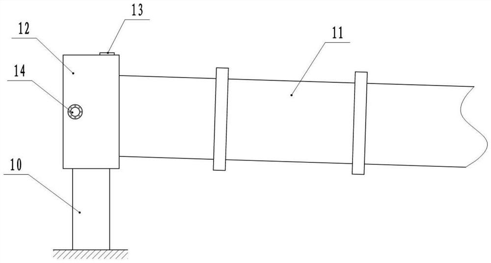
[0038] combine figure 2 As shown, the difference from Embodiment 1 is that in this embodiment, the auxiliary air hole 14 is located in the middle of the outer wall; through model simulation calculations, a conclusion similar to that of Embodiment 1 is obtained, that is, the air excess coefficient of hazardous waste incineration is controlled at 0.8 ~1.0 to control the air supply, and the thermal loss rate of hazardous waste incineration of the rotary kiln is less than 3%.


PUM


Abstract

The invention relates to the technical field of hazardous waste incineration, and particularly discloses a hazardous waste rotary kiln incineration air supply method. The method is achieved through animproved air supply structure. The air supply structure comprises a supporting frame, a rotary drum and a kiln head cover. The kiln head cover is cylindrical, a main air hole and an auxiliary air hole are formed in the side wall of the kiln head cover, the main air hole is located in the top of the kiln head cover, the main air hole and the auxiliary air hole are not located in the same circumferential line of the kiln head cover, the main air hole is close to the rotary drum, and the auxiliary air hole is away from one side of the rotary drum. When the temperature in the rotary drum rises toa preset value, air is supplied into the kiln head cover from the main air hole and the auxiliary air hole, and the air speeds of the main air hole and the auxiliary air hole are consistent. Throughmodel simulation, the air excess coefficient of hazardous waste incineration is controlled to range from 0.8 to 1.0 to adjust the air supply amount, the rotary turbulence flow field of the scheme is obtained through calculation, the hazardous waste incineration heat ignition loss rate of a rotary kiln can be lower than 3%, thus, the scheme can guarantee the much lower heat ignition loss rate on the premise that the low excess coefficient is guaranteed, and the combustion rate is increased.

Description

technical field [0001] The invention relates to the technical field of hazardous waste incineration, in particular to an air supply method for hazardous waste rotary kiln incineration. Background technique [0002] A large amount of domestic garbage and waste are produced every day in the country. Most of these domestic garbage and waste contain toxic and harmful substances. If they are discharged indiscriminately, they will pollute the environment. Therefore, these hazardous wastes must be treated before they can be discharged. At present, the rotary kiln is mainly used to incinerate hazardous waste. The thermal ignition loss rate of the ash after hazardous waste incineration is the most powerful basis for judging whether the rotary kiln is normal or not, and can calculate the completion status of incineration. [0003] Usually, if the air passing into the rotary kiln cannot be sufficiently diffused, the formed flow field is not fully covered, and the moving speed along th...

Claims


Application Information

Patent Timeline
Patent Type & Authority Applications(China)
IPC IPC(8): F23G7/00F23G5/20F23G5/44
CPCF23G7/00F23G5/20F23G5/44F23G2203/20
Inventor 胡茂丽林辉荣马泽洲郑伟毛海波
Owner XINZHONGTIAN ENVIRONMENTAL PROTECTION
Why Eureka
Try Eureka